
Fault diagnosis method for piston-type air compressor crankcase rolling bearing

A rolling bearing and fault diagnosis technology, which is applied in the testing of mechanical components, testing of machine/structural components, measuring devices, etc., can solve fault missed detection, periodic impact characteristic interference, and difficult to solve piston air compressor fault bearing diagnosis Problems and other problems, to achieve the effect of fast and accurate identification

Inactive Publication Date: 2019-01-11
INST OF LASER & OPTOELECTRONICS INTELLIGENT MFG WENZHOU UNIV
View PDF3 Cites 8 Cited by
  • Summary
  • Abstract
  • Description
  • Claims
  • Application Information

AI Technical Summary

Problems solved by technology

[0003] The key to fault diagnosis of rolling bearings is to identify the periodic shock characteristics caused by fault excitation, but these periodic shock characteristics are easily disturbed by environmental noise and other vibration sources
Due to the complex structure and poor working environment of the piston air compressor, its periodic impact characteristics are easily disturbed by the environmental noise and the vibration of various internal components. The vibration signal of the faulty rolling bearing usually presents nonlinear and non-stationary characteristics. The traditional The fault identification rate of the diagnostic method is low and there are serious fault missed detections, which makes it difficult to solve the problem of faulty bearing diagnosis of piston air compressors

Method used


Image

  • Fault diagnosis method for piston-type air compressor crankcase rolling bearing
  • Fault diagnosis method for piston-type air compressor crankcase rolling bearing
  • Fault diagnosis method for piston-type air compressor crankcase rolling bearing

Examples


Embodiment Construction

[0041] In order to make the object, technical solution and advantages of the present invention clearer, the present invention will be further described in detail below in conjunction with the accompanying drawings.

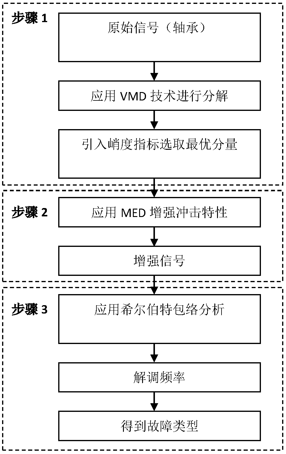
[0042] The specific steps of a fault diagnosis method for crankcase rolling bearings of piston air compressors are as follows:

[0043] First, the rolling bearing vibration signal collected from the piston air compressor is used as the original signal for VMD processing to obtain a series of modal components containing fault information. The detailed steps of VMD processing are as follows:

[0044] VMD technology can decompose the non-stationary signal y(t) into a group of modal components located near the center frequency, and the signal y(t) can be expressed as the following formula:

[0045] y(t)=∑ k u k (1)

[0046] The essence of VMD is to solve the optimal solution of the constrained variational model, which is given by the following formula:

[0047] ...


PUM


Abstract

The invention discloses a fault diagnosis method for a piston-type air compressor crankcase rolling bearing, and belongs to the field of piston-type air compressor maintenance. The fault diagnosis method specifically comprises the steps that firstly, a variational mode decomposition (VMD) technology is adopted to decompose an original vibration signal of the piston-type air compressor rolling bearing, and mode components with the given number are obtained; then Kurtosis index is applied to all the mode components obtained by decomposition, thus respective Kurtosis values are obtained, the modecomponent corresponding to the maximum Kurtosis value is selected as the optimal component, and minimum entropy deconvolution (MED) is applied to the optimal component to enhance the periodic impactcharacteristics of fault excitation; and finally, Hilbert envelope analysis is used for demodulating the fault frequency of the enhanced signal, and a fault diagnosis result is obtained by comparing the fault frequency with a fault theoretical calculation frequency value. According to the fault diagnosis method for the piston-type air compressor crankcase rolling bearing, the fault type of the piston-type air compressor crankcase rolling bearing can be identified quickly and effectively, and the fault diagnosis method has the advantages of high reliability and good engineering feasibility.

Description

technical field [0001] The invention belongs to the field of maintenance of piston air compressors, and relates to a method for diagnosing faults of crankcase rolling bearings of piston air compressors. Background technique [0002] Piston air compressors are called "general machinery" because they are widely used in many industrial fields such as machinery, metallurgy, electronic power, packaging, mining, etc., and their huge usage also highlights various faults. Engine crankcase failure accounts for a large proportion. As one of the important components in the crankcase, the rolling bearing not only supports the balanced operation of the crankshaft, but also bears the heavy responsibility of transmitting motion and power. Once the rolling bearing fails, it will cause abnormal noise and wear of the connecting rod, and cause direct economic losses. and heavy casualties. Therefore, in order to reduce the misdiagnosis rate of piston air compressor rolling bearing faults and ...

Claims


Application Information

Patent Timeline
IPC IPC(8): G01M13/045
CPCG01M13/045
Inventor 向家伟刘辉
Owner INST OF LASER & OPTOELECTRONICS INTELLIGENT MFG WENZHOU UNIV
Learn More