Ducted shaftless power generation device

A power generation device, ducted technology, applied in the direction of engine components, machines/engines, mechanical equipment, etc., can solve problems such as low power conversion rate

Pending Publication Date: 2019-01-11
南充西南石油大学设计研究院有限责任公司
View PDF1 Cites 1 Cited by
  • Summary
  • Abstract
  • Description
  • Claims
  • Application Information

AI Technical Summary

Problems solved by technology

In the above scheme, the turbine rotates around the shaft to generate electricity, which has a

Method used


Image

  • Ducted shaftless power generation device

Examples


Embodiment Construction

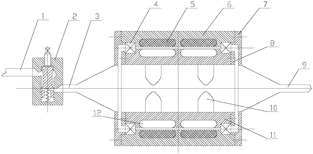
[0012] The present invention will be further described below in conjunction with accompanying drawing.

[0013] Such as figure 1 As shown, the ducted shaftless power generation device of the present invention includes an intake pipeline 1, a throttle valve 2, a differential pressure power generation system and an exhaust pipeline 9. The intake pipeline 1 is connected to the inlet end of the throttle valve 2, and the throttle The outlet end of the throttle valve 2 is connected to the intake end of the differential pressure power generation system, and the exhaust end of the differential pressure power generation system is connected to the exhaust pipeline 9, that is, the throttle valve 2 and the differential pressure power generation system are connected in series to the intake pipeline 1 and the exhaust gas pipeline. Between gas pipelines 9.

[0014] The differential pressure power generation system includes a stator 6 and a rotor 11. The inner side of the stator 6 is connect...


PUM


Abstract

The invention discloses a ducted shaftless power generation device and relates to the field of power generation. A technical problem is solved by providing the ducted shaftless power generation devicecapable of using pressure difference during natural gas production and transportation to generate power. An adopted technical scheme is that the ducted shaftless power generation device comprises a gas inlet pipeline, a throttle valve, a pressure difference power generation system and a gas exhaust pipeline; the throttle valve and the pressure difference power generation system are connected between the gas inlet pipeline and the gas exhaust pipeline in series; the pressure difference power generation system comprises a stator and a rotor; the two ends of the stator are correspondingly sealedby using cover plates; the two cover plates are correspondingly a gas inlet end and a gas exhaust end of the power generation system; a stator coil is arranged in the stator; the internal side of thestator is connected with the rotor through a rotating piece; a rotor magnet is arranged in the rotor; an impeller is arranged on the internal side of the rotor; and the impeller is fixedly mounted onthe internal side of the rotor. As the middle part of the stator and the middle part of the rotor are shaftless, a gas flow passage is smooth, the resistance of the gas flow passage is small, and maximized energy conversion is realized. As the heat generated by the pressure difference power generation system is brought away with gas, a high temperature phenomenon is avoided.

Description

technical field [0001] The invention relates to the field of power generation, in particular to a device for generating power through an airflow with a pressure difference. Background technique [0002] During the production and transportation of natural gas, there is a flow pressure difference between the high-pressure wellhead of natural gas and the pressure of the gas pipeline. The authorized announcement number is CN 103334891 B, and the patent announced on August 26, 2015 discloses a power generation device that utilizes natural gas flowing pressure difference kinetic energy to generate electricity. The power generation device includes a main pipeline, an inlet pressure regulating valve, an outlet pressure regulating valve and a differential pressure power generation system, and the inlet pressure regulating valve, the differential pressure power generation system and the outlet pressure regulating valve are sequentially arranged in series on the main pipeline. Among t...

Claims


Application Information

Patent Timeline
IPC IPC(8): F01D15/10F01D17/10
CPCF01D15/10F01D17/10
Inventor 张泉
Owner 南充西南石油大学设计研究院有限责任公司
Why Eureka
Try Eureka