Sound-proof door structure
A technology for soundproof doors and soundproof strips, which is applied to soundproof doors/windows, door leaves, windows/doors, etc., which can solve problems such as abnormal reflection, affecting sound insulation effect, and insufficiency of brain nerves, so as to improve sound insulation performance and reduce noise obvious effect
- Summary
- Abstract
- Description
- Claims
- Application Information
AI Technical Summary
Problems solved by technology
Method used
Image
Examples
Embodiment 1
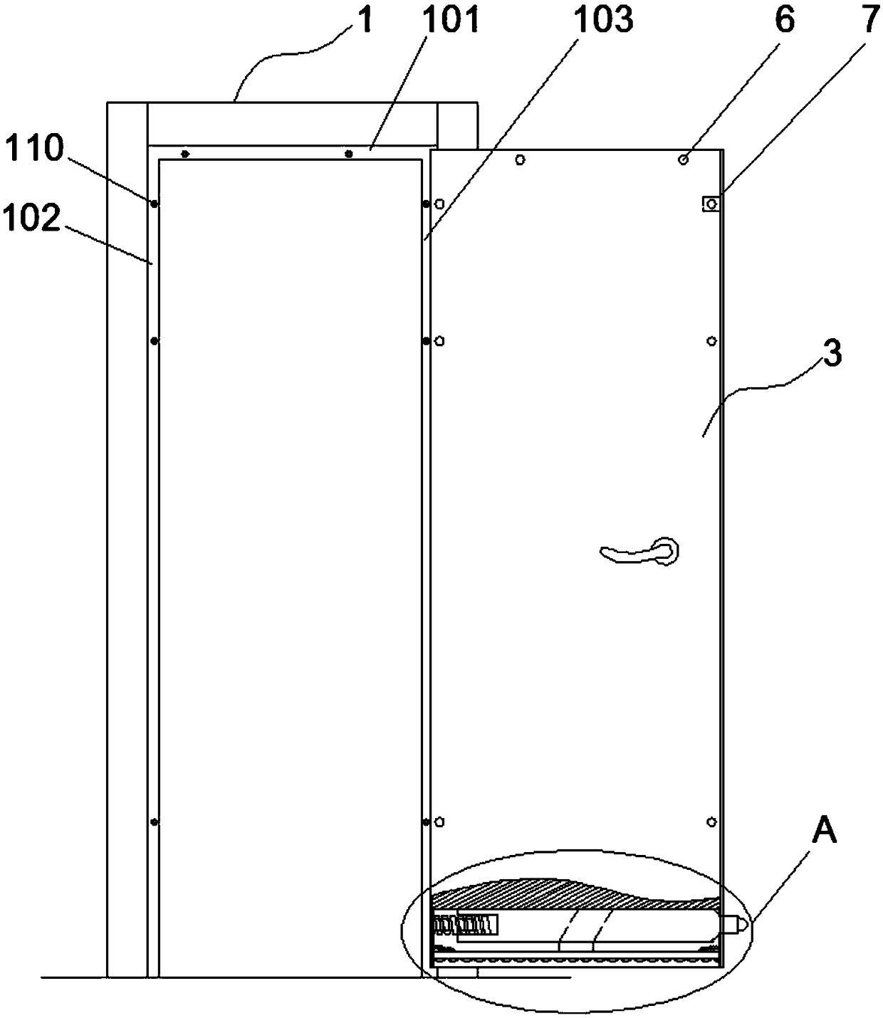
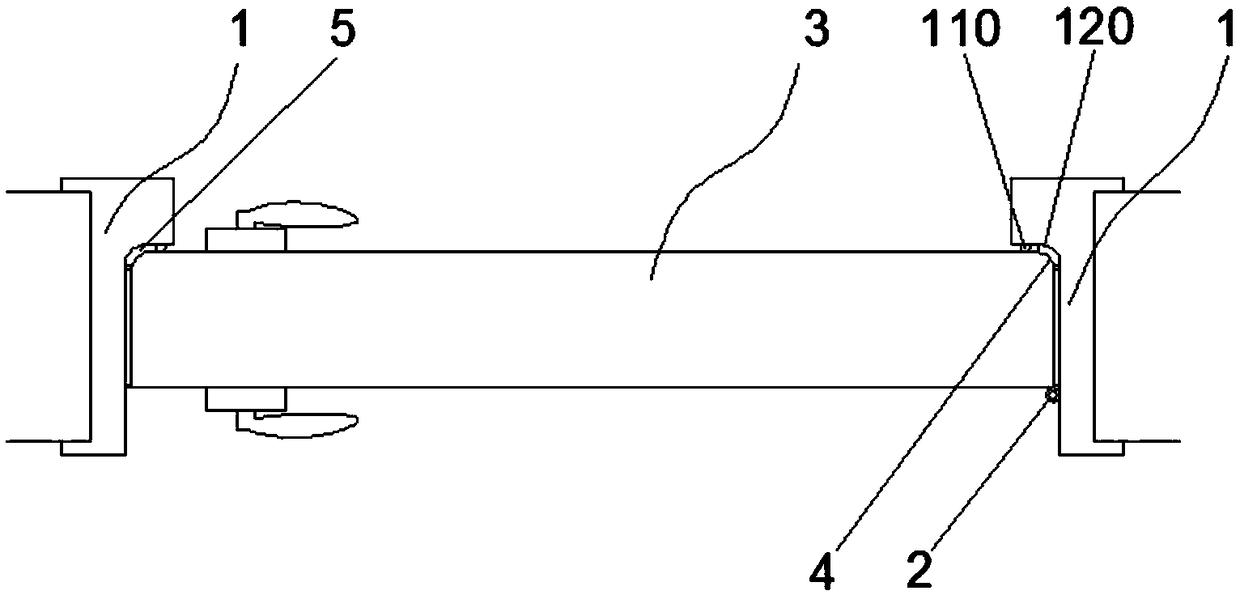
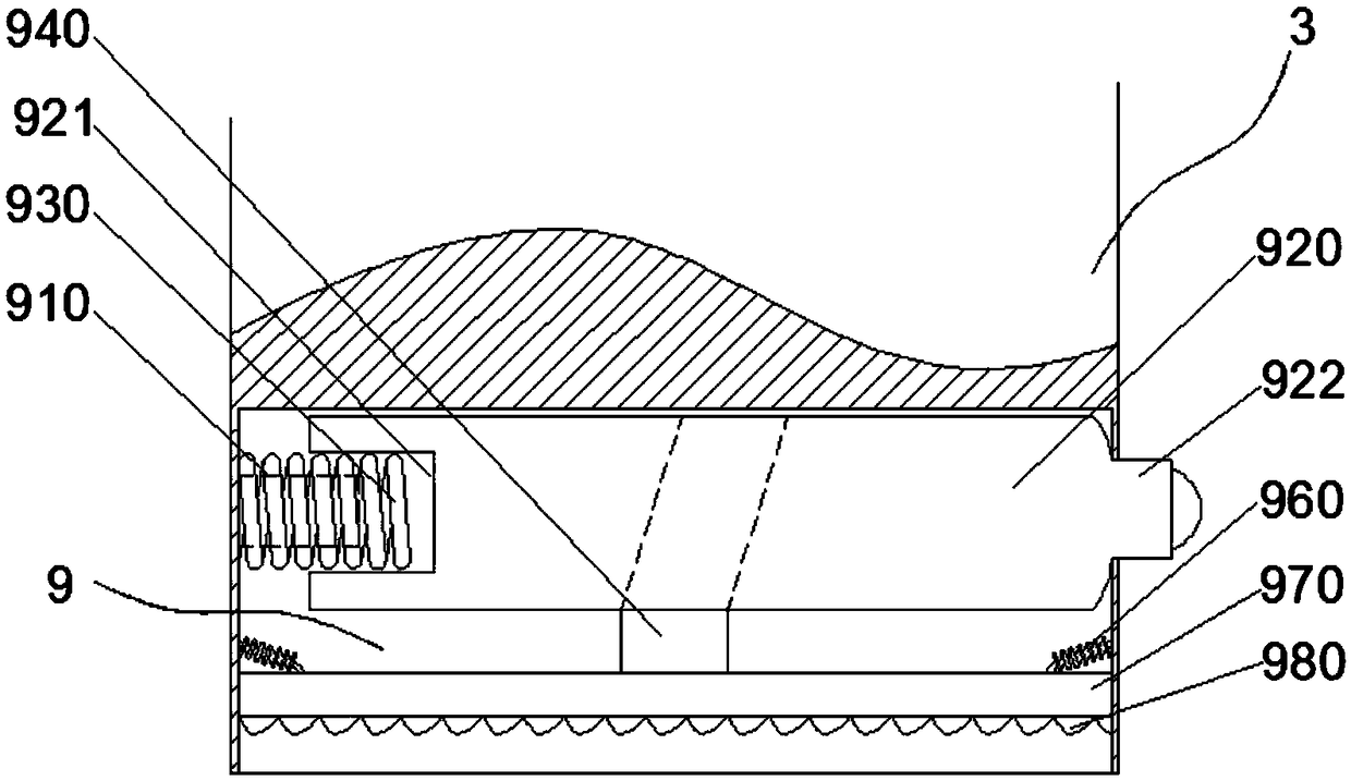
[0038] like figure 1 and figure 2 As shown, the present invention is a soundproof door structure, including: a door frame 1 and a door panel 3 arranged on the wall, the door panel 3 is connected to the door frame 1 through a hinge 2, and the door panel 3 is opened inwardly Direction, inward opening direction not only has good sound insulation effect, but also has a good anti-theft effect. The upper frame 101, the left frame 102 and the right frame 103 of the door frame 1 are respectively provided with an inner arc surface 120 of the same radian, and a sound insulation strip 5 is pasted and fixed on the inner arc surface 120, in order to make the sound insulation strip 5 and the inner arc surface The bonding effect of the arc surface 120 is better, and the sound insulation strip 5 is designed to be the same as the arc of the inner arc surface 120 . The door panel 3 is provided with an outer arc surface 4 corresponding to the inner arc surface 120 of the door frame 1, and the...
Embodiment 2
[0043] The difference between Embodiment 2 and Embodiment 1 lies in that the structure of the contact part of the horizontal rod 920 and the lifting mechanism is different. like Image 6 As shown, the bottom of the horizontal rod 920 in contact with the lifting mechanism is a downwardly protruding wave-shaped protrusion 924. The lifting mechanism includes a vertical rod 950, a horizontal baffle 970 and a roller 951. The horizontal baffle 970 Fixed on the bottom of the pole, the roller 951 is arranged on the top of the pole 950 , and the roller 91 is in rolling contact with the wave-shaped protrusion 924 at the bottom of the horizontal pole 920 . When the protruding head 922 is located inside the bottom channel 9, the roller 951 is located on a wavy protrusion 924 of the horizontal rod 920, the position of the lifting mechanism moves down, and the sound-absorbing strip 980 is located outside the bottom channel 9; when the protruding head 922 is located on the bottom channel Wh...
Embodiment 3
[0045] Embodiment 3 On the basis of Embodiment 1 or Embodiment 2, the following solutions are proposed for the gap between the left and right sides and the upper part of the door panel 3 and the door frame 1, resulting in no sound insulation. like figure 1 As shown, on the surface of the upper frame 101, the left frame 102 and the right frame 103 of the door frame 1, a plurality of tapered protrusions 110 are respectively arranged at intervals along the length direction or width direction of the door panel 3, between the door panel 3 and the door frame 1 A blind hole 6 corresponding to each tapered protrusion 110 is provided on the mating surface, and a side channel 7 communicating with the blind hole 6 is provided on the side wall of the door panel 3, and an extension mechanism is provided in the side channel 7 , the protruding end of the extending mechanism is connected to the sealing edge strip 8, and the sealing edge strip 8 is located in the side channel 7, and the sealin...
PUM
 Abstract
Description
Claims
Application Information
 - R&D
- Intellectual Property
- Life Sciences
- Materials
- Tech Scout
- Unparalleled Data Quality
- Higher Quality Content
- 60% Fewer Hallucinations
Browse by: Latest US Patents, China's latest patents, Technical Efficacy Thesaurus, Application Domain, Technology Topic, Popular Technical Reports.
© 2025 PatSnap. All rights reserved.Legal|Privacy policy|Modern Slavery Act Transparency Statement|Sitemap|About US| Contact US: help@patsnap.com


