Double-sided material falling device

A blanking device and double-sided technology, applied in the direction of packaging, transportation and packaging, conveyors, etc., can solve the problem that the two-way blanking of steel pipes cannot be applied

Pending Publication Date: 2019-01-11
江苏省南扬机械制造有限公司
View PDF1 Cites 2 Cited by
  • Summary
  • Abstract
  • Description
  • Claims
  • Application Information

AI Technical Summary

Problems solved by technology

But its shortcoming is: when the welded pipe after cutting and forming is transported, some of the steel pipes may have defects, which are unqualified products, and the qualified steel pipes and defective steel pipes need to be cut separately. This device is suitable for spherical workpieces and cannot Suitable for bi-directional feeding of steel pipes with a certain length

Method used


Image

  • Double-sided material falling device
  • Double-sided material falling device
  • Double-sided material falling device

Examples


Embodiment 1

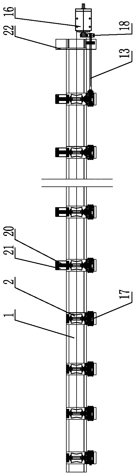
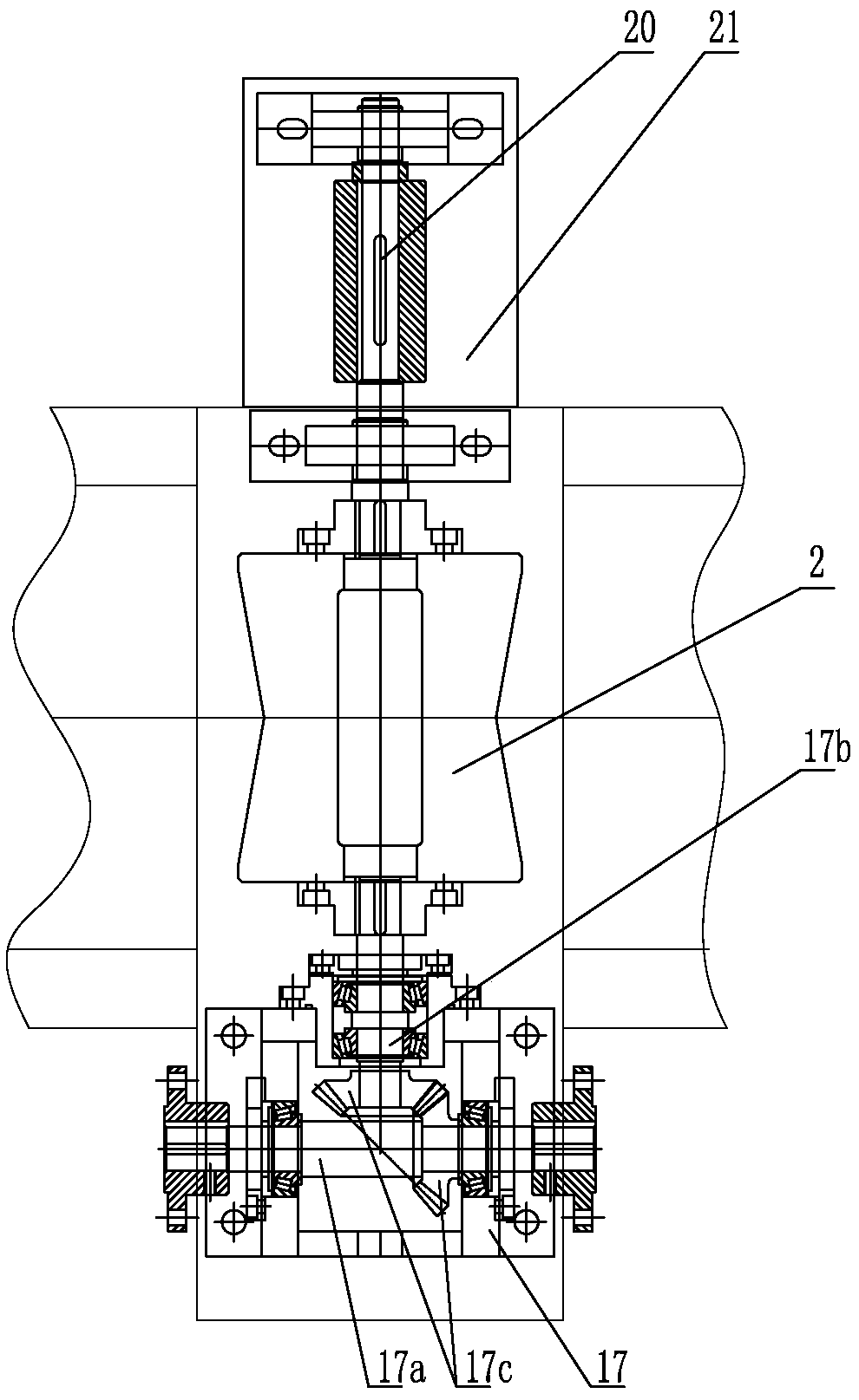
[0031] like Figure 1-7As shown, it is a double-sided blanking device, including a machine base 1, on which a number of rotatable transmission rollers 2 are arranged sequentially from left to right, and the transmission rollers 2 are arranged horizontally, and each transmission roller 2 is connected to the rotating drive Mechanism-transmission connection, the pipe fitting 24 is horizontally supported on the transmission roller 2, and the machine base 1 is provided with a pushing mechanism that can push the pipe fitting 24 to the front side blanking area and the rear side blanking area respectively. The rollers 2 are staggered from each other. Described pushing mechanism comprises at least one group of bidirectional pushing assembly, and bidirectional pushing assembly comprises front blanking plate 3 and rear blanking plate 4, and bidirectional pushing assembly is positioned at pipe fitting 24 below, and the upper side of front blanking plate 3 is inclined and Corresponding to...

Embodiment 2

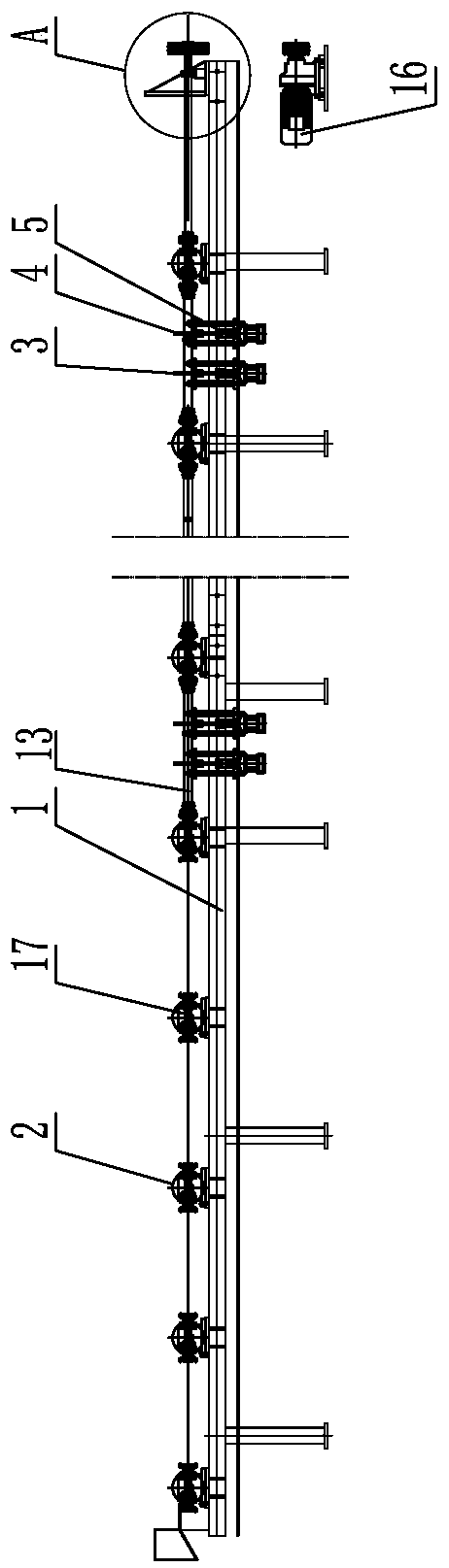
[0034] like Figure 8-13 As shown, the difference from Example 1 is that the pusher mechanism includes a number of supports 6 arranged at intervals from left to right on the base 1, the top of the support 6 is provided with a rotating shaft 7, and the rotating shaft 1 7 is parallel to the axis of the pipe fitting 24, and one end of the rotating shaft 7 is provided with a blanking wheel 8, and the outer circumference of the blanking wheel 8 is uniformly provided with a number of pusher arms 8a, and the pusher arm 8a is correspondingly arranged with the pipe fitting 24, and the pusher arm 8a and the transmission roller 2 are mutually staggered, and the first rotating shaft 7 is connected with the second rotating drive mechanism. The second rotating drive mechanism includes a sprocket 9 sleeved on the other end of the rotating shaft 7, the bottom of the support 6 is provided with a rotating shaft 10, the rotating shaft 10 is located below the machine base 1, and the rotating shaf...


PUM


Abstract

The invention discloses a double-sided material falling device in the field of material falling devices. The double-sided material falling device comprises a machine base; a plurality of rotatable transmission rollers are sequentially arranged on the machine base from left to right; the transmission rollers are horizontally arranged; each transmission roller is in transmission connection with a rotary driving mechanism; pipe fittings are horizontally supported on the transmission rollers; pushing mechanisms capable of pushing the pipe fittings to a front material falling area and a rear material falling area correspondingly are arranged on the machine base; and the pushing mechanisms and the transmission rollers are arranged in a mutually staggered manner. Cut and formed steel pipes can correspondingly fall into the front material falling area and the rear material falling area, the qualified pipe fittings and defective pipe fittings can be sorted out, and the material falling efficiency is higher.

Description

technical field [0001] The invention belongs to the field of blanking devices, in particular to a bilateral blanking device. Background technique [0002] In the prior art, when the welded pipe is produced and processed, the steel coil is first fixed on the discharge rack, and the end of the steel strip is sent to the leveling mechanism through the storage device for leveling, and then the steel strip is sequentially entered into the roll forming machine to form a tubular shape. , and then the pipe seam is welded, squeezed and closed by the welding device, tracked and cut by the cutting device, and then falls on the conveying device. The above processes are all completed continuously. When the cut and formed welded pipe is transported on the conveying device, it needs to be unloaded. [0003] The Chinese patent database discloses an automatic two-way blanking machine, its patent application number: 201711413624.6; application date 2017.12.24; its structure includes a machin...

Claims


Application Information

Patent Timeline
Patent Type & Authority Applications(China)
IPC IPC(8): B65G47/82B65G47/24B65G47/74B65G47/46B07C5/00B07C5/36B65B27/10
CPCB65G47/82B07C5/00B07C5/36B65B27/10B65G47/24B65G47/46B65G47/74B65G2201/0217
Inventor 王正田颜兴林颜浩刘成
Owner 江苏省南扬机械制造有限公司
Why Eureka
Try Eureka