Billet ejection system and method of billet continuous casting machine

A technology of billet continuous casting and billet casting, which is applied in the field of billet discharge system of billet continuous casting machine, which can solve problems such as high casting speed, low billet discharge efficiency, and roller scratches, so as to avoid roller scratches and casting billet, improve the efficiency of blanking, and avoid the effect of wear

Active Publication Date: 2021-07-13
CHINA NAT HEAVY MACHINERY RES INSTCO
View PDF5 Cites 1 Cited by
  • Summary
  • Abstract
  • Description
  • Claims
  • Application Information

AI Technical Summary

Problems solved by technology

[0006] A billet discharge system and method for a billet continuous casting machine provided by the present invention. The first purpose is to overcome the problems in the prior art that cannot meet the requirements of high casting speed, short fixed length, and fast-paced billet discharge; the second purpose is to overcome the existing In the technology, when the billet is discharged by the traditional through-roller, the casting billet wears the roller and the roller scratches the billet, and the billet discharge efficiency is low.

Method used


Image

  • Billet ejection system and method of billet continuous casting machine
  • Billet ejection system and method of billet continuous casting machine
  • Billet ejection system and method of billet continuous casting machine

Examples


Embodiment 1

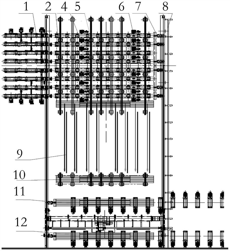
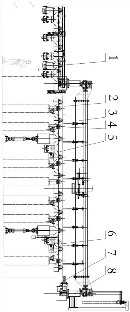
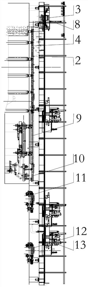
[0032] Such as Figure 1-3 As shown, a billet discharge system of a billet continuous casting machine includes a conveying roller table 1, a steel transfer machine 3, a steel transfer rail 4, a billet discharge roller table 5, a detection device 6, a trolley rail 8, and a steel scooping machine 13 , the cold delivery roller table 11, the hot delivery roller table 12 and the temporary storage device, the conveying roller table 1 and the billet roller table 5 are arranged horizontally from left to right in sequence, and the billet roller table 5 is vertically connected with the steel transfer track 4, The right end of the billet roller table 5 is longitudinally connected to the trolley track 8, the detection device 6 is connected to the billet roller table 5, the steel moving machine 3 and the steel scooping machine 13 are sequentially connected to the trolley rail 8 from back to front, and the steel moving track 4 The front of the machine is provided with a temporary storage de...

Embodiment 2

[0045] A billet discharging method of a billet continuous casting machine, comprising the steps of:

[0046] When the billet 2 needs to be cold-delivered, it includes the following steps: when the detection device 6 detects that there is a billet 2 above the billet roller table 5, the billet roller table 5 is lowered to a low position, and the billet 2 falls on the top of the steel moving track 4, and the billet 2 is moved The steel machine 3 moves the casting slab 2 to the top of the step-and-turn cooling bed 9, and the step-and-turn cooling bed 9 transports the casting slab 2 above to the temporary storage stand 10, and the steel scooping machine 13 stores the cast slab on the stand 10. The billet 2 is moved to the top of the cold delivery roller table 11, and the casting billet 2 is transported to the destination area by the cold delivery roller table 11;

[0047] When the billet 2 needs hot delivery, the steps include the following steps: when the detection device 6 detect...


PUM


Abstract

The invention belongs to the technical field of continuous casting in the metallurgical industry, and particularly provides a billet ejection system and method of a billet continuous casting machine. The billet ejection system comprises a conveying roller way, a steel moving machine, a steel moving track, a billet ejection roller way, a detection device, a trolley track, a steel fishing machine, a cold conveying roller way, a hot conveying roller way and a temporary storage device. The conveying roller way and the billet ejection roller way are sequentially arranged transversely from left to right, the steel moving track is longitudinally connected to the billet ejection roller way, the right end of the billet ejection roller way is longitudinally connected with the trolley track, the detection device is connected with the billet ejection roller way, the steel moving machine and the steel fishing machine are sequentially connected to the trolley track from back to front, and the temporary storage device, the cold conveying roller way and the hot conveying roller way are sequentially arranged in front of the steel moving rail from back to front. The problem that in the prior art, the billet ejection requirements of high pulling speed, short sizing and fast pace cannot be met is solved, billet ejection is flexible according to requirements, the billet ejection efficiency is improved, and the cold conveying rate and the hot conveying rate of casting billets are increased.

Description

technical field [0001] The invention belongs to the technical field of continuous casting in the metallurgical industry, and in particular relates to a billet discharging system and method of a billet continuous casting machine. Background technique [0002] The metallurgical industry, especially the continuous casting field, is affected by its own product positioning, process route, investment, plant conditions and other factors, and the layout of its workshops is not the same. [0003] In order to adapt to different production conditions and meet different blanking process requirements, different blanking methods are required. [0004] The existing billet continuous casting machine uses a scooping machine to discharge the billet. However, due to the limited capacity of the scooping machine, for high casting speed and short fixed-length billets, the billet discharge cycle is fast, and the scooping machine is very fast. Can not meet the requirements of the billet rhythm. ...

Claims


Application Information

Patent Timeline
Patent Type & Authority Applications(China)
IPC IPC(8): B22D11/128
CPCB22D11/1284
Inventor 何保卫何博章裕琳李积文蒋军关燚
Owner CHINA NAT HEAVY MACHINERY RES INSTCO
Why Eureka
Try Eureka