Blank holder device of tank body

A technology of a side blanking device and a tank body is applied in the field of side blanking devices of a tank body, which can solve the problems of poor molding effect, high difficulty, easy deviation of the tank body, etc., and achieve the effects of simple operation and high blanking efficiency.

Inactive Publication Date: 2018-08-17
ANHUI YILIANG TANK IDUSTRY TECH CO LTD
View PDF6 Cites 1 Cited by
  • Summary
  • Abstract
  • Description
  • Claims
  • Application Information

AI Technical Summary

Problems solved by technology

[0002] In the field of tea production, iron cans are usually used to hold tea leaves, and iron cans often need to use pressing machines during processing. The existing patent 205414193 discloses a fixing fixture for can body processing. The actual production of this device The operation is: the worker sits in front of the fixture, puts the tank body to be pressed on the fixed column, and then pushes the fixed column to the bottom of the pressing machine to process the tank body. When fixed and clamped, the degree of cooperation between the fixed column and the tank body should be high, but when the size difference between the fixed column and the tank body is small, although the tank body is not easy to shake during pressing, it will be more difficult for workers to insert the tank body If the size of the fixed column is adjusted to make it slightly smaller than the inner wall of the tank, although the worker can quickly put the tank on the fixed column, the fixed column and The gap between the tanks will be too large, and the tanks are easy to deviate, making the positioning of the tanks inaccurate, resulting in poor molding effect after pressing

Method used


Image

  • Blank holder device of tank body
  • Blank holder device of tank body
  • Blank holder device of tank body

Examples


Embodiment Construction

[0014] Preferred embodiments of the present invention will be described in detail below in conjunction with the accompanying drawings.

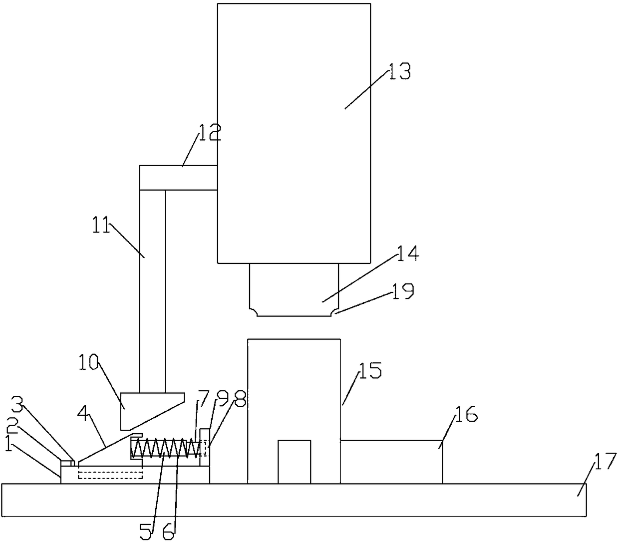
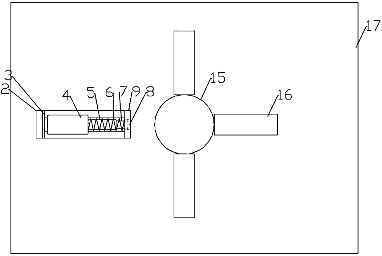
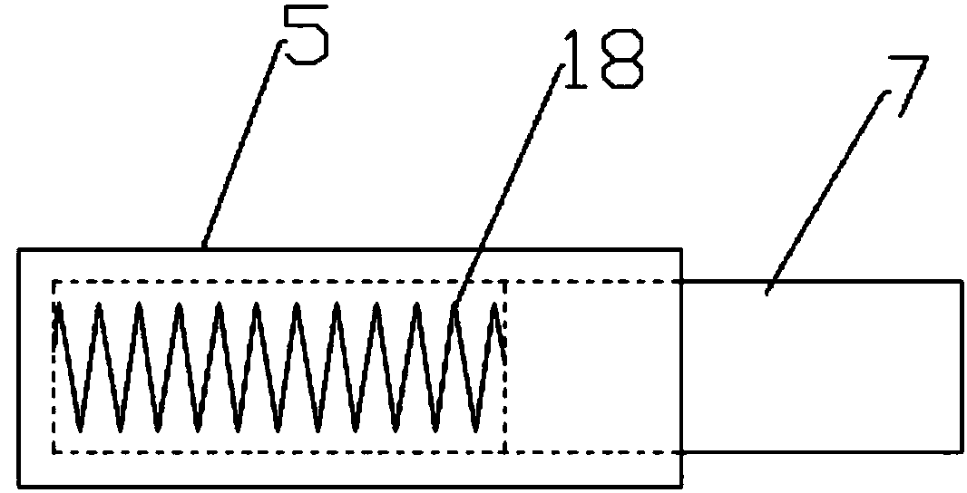
[0015] Figure 1-5 A specific embodiment of the present invention is shown: a crimping device for a tank body 15, including a workbench 17, a pressing device 13 is arranged above the workbench 17, and the pressing device 13 performs linear motion in the vertical direction. The lower end of the pressing device 13 is provided with an indenter 14, and the indenter 14 moves linearly in the vertical direction. The side of the pressing device 13 is provided with a cross bar 12, and the cross bar 12 is connected with a strut 11. The lower end of strut 11 is provided with upper inclined wedge 10, and the bottom of described upper inclined wedge 10 is provided with bottom plate 1, and described bottom plate 1 is provided with chute, and described chute is provided with lower inclined wedge 4, and described lower inclined wedge 4 The inclined wedge 4 ...


PUM


Abstract

The invention discloses a blank holder device of a tank body. The blank holder device comprises a working table, and a pressing device is arranged above the working table; the lower end of the pressing device is provided with a pressure head, and the side of the pressing device is provided with a cross bar connected to a supporting rod; the lower end of the supporting rod is provided with an upperwedge, and a baseplate is arranged below the upper wedge; the baseplate is provided with a sliding chute which is internally provided with a lower wedge, and the side of the wedge is provided with acircular groove which is internally provided with a casing pipe; the casing pipe is internally provided with a slidable ejector rod of which the tail part is provided with a spring II, and the springII is connected to the bottom of the casing pipe; the exterior of the casing pipe is connected to a spring I in a sleeved manner, and the spring I is fixed to the side of the lower wedge; and one endof the baseplate is provided with a stop plate which is provided with a circular hole, and the working table is further provided with three locating blocks distributed along the circumference of the pressure head. According to the blank holder device, the outer wall of the tank body is clamped through the ejector rod and the three locating blocks, and the tank body needs to be placed at the position of the locating blocks only; the operation is simple, and people can operate the blank holder device without training; the blank holder efficiency is high, and the blank holder device is applicablefor quick blank holder operation of the tank body.

Description

technical field [0001] The invention relates to the field of tea can processing, in particular to an edge pressing device for a can body. Background technique [0002] In the field of tea production, iron cans are usually used to hold tea leaves, and iron cans often need to use pressing machines during processing. The existing patent 205414193 discloses a fixing fixture for can body processing. The actual production of this device The operation is: the worker sits in front of the fixture, puts the tank body to be pressed on the fixed column, and then pushes the fixed column to the bottom of the pressing machine to process the tank body. When fixed and clamped, the degree of cooperation between the fixed column and the tank body should be high, but when the size difference between the fixed column and the tank body is small, although the tank body is not easy to shake during pressing, it will be more difficult for workers to insert the tank body If the size of the fixed colu...

Claims


Application Information

Patent Timeline
IPC IPC(8): B21D51/26
CPCB21D51/2615B21D51/2692
Inventor 邢永义邢婷王伟
Owner ANHUI YILIANG TANK IDUSTRY TECH CO LTD
Why Eureka
Try Eureka