Quality control method and device for blade linear friction welding joint

A linear friction welding and control device technology, applied in welding equipment, manufacturing tools, non-electric welding equipment, etc., can solve problems such as waste of precious metals, welding defects, and reduce welding area, so as to achieve the effect of reducing waste and uniform heat production

Active Publication Date: 2019-01-11
AVIC BEIJING AERONAUTICAL MFG TECH RES INST
View PDF5 Cites 2 Cited by
  • Summary
  • Abstract
  • Description
  • Claims
  • Application Information

AI Technical Summary

Problems solved by technology

In order to avoid defects affecting the quality of welded joints, it is necessary to leave a large margin to ensure the removal of unwelded defects, resulting in waste of precious metals
[0003] In addition, in linear friction welding, a rectangular or leaf-shaped cross-section that can accommodate the size of the blade is usually used. When a rectangular cross-section is used for welding, the above-mentioned unwelded defects are prone to occur at the corners of the rectangle.
When the leaf-shaped section is selected, it is not specified how to optimize the profile to ensure that the welding area is reduced and the quality of the welded joint is ensured. Waste of metal, increase the friction pressure of the welding process; or the welding section is too small, resulting in insufficient local heat generation of the welding section, resulting in welding defects, affecting the quality of the joint

Method used


Image

  • Quality control method and device for blade linear friction welding joint
  • Quality control method and device for blade linear friction welding joint

Examples


Embodiment 1

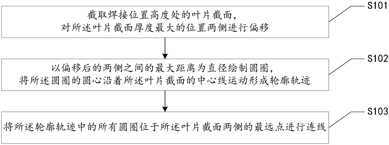
[0029] Such as figure 1 As shown, this embodiment proposes a method for quality control of blade linear friction welding joints, the method comprising:

[0030] S101. Intercepting the section of the blade at the height of the welding position, and offsetting the two sides of the position where the thickness of the section of the blade is the largest.

[0031] Specifically, in this embodiment, a certain welding allowance can be reserved by offsetting the two sides of the position where the thickness of the blade section is the largest. If you choose a position with a smaller thickness, it is easy to have no margin in other positions, resulting in poor welding. However, if the margin is too large, it will affect the frictional pressure of the welding process and also cause welding defects. Therefore, in this embodiment, the margin is set between 2 mm and 5 mm, that is, the distance between the two sides after the shift and the original position is 2 mm to 5 mm.

[0032] S102....

Embodiment 2

[0039] This embodiment proposes a quality control device for linear friction welding joints of blades, the device includes a processor, and the processor is embedded with operational instructions executable by the processor, and has performed the following operations:

[0040] Obtain the blade section at the height of the welding position;

[0041] offsetting the two sides of the position where the section thickness of the blade is the largest;

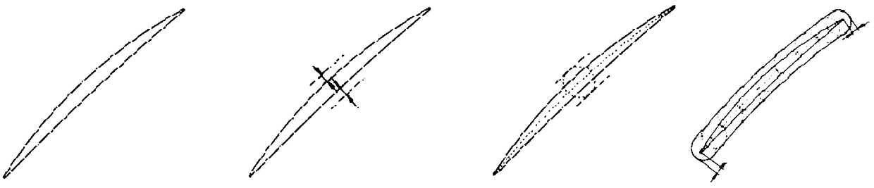
[0042] Draw a circle with the maximum distance between the two sides after the offset as the diameter, and the center of the circle is the midpoint of the maximum distance line segment between the two sides after the offset;

[0043] moving the center of the circle along the centerline of the blade section to form a contour track;

[0044] Connect the farthest points of all the circles in the contour trajectory on both sides of the blade section, and the area enclosed by the two line segments after the connection and the circles at b...


PUM


Abstract

The invention discloses a quality control method for a blade linear friction welding joint. The method comprises the steps that the cross section of a blade at the height of a welding position; two sides of the position, which is the highest in thickness, of the cross section of the blade are displaced; a circle is drawn by taking the largest distance between the two sides after displacement as the diameter; the center of the circle is the middle spot of the largest distance segment between the two sides after displacement; the circle center of the circle moves along the central line of the cross section of the blade to form an outline trajectory; the farthest spots, located on two sides of the cross section of the blade, of all circles in the outline trajectory are connected; and the zonewhich is surrounded by the circles on the two ends of the cross section of the blade and two segments formed after connection is taken as the cross section zone of welding. The invention further discloses a blade linear friction welding joint quality control device. By adopting the quality control method and device, the problem that an unfused defect is prone to being formed at an angle part of atraditional rectangular or diamond cross section is overcome; the welding area of a component is effectively decreased, and the quality of the welding joint is ensured; and waste of precious metal isgreatly reduced.

Description

technical field [0001] The present application relates to the field of welding, in particular to a method and device for quality control of blade linear friction welding joints. Background technique [0002] Linear friction welding technology is a solid phase welding technology, which has unique advantages in titanium alloy welding, and has excellent joint performance. The use of linear friction welding technology to manufacture the blisk has many other advantages, such as the self-cleaning effect in the welding process, the joint is forged structure, the welding process is stable and reliable, and the quality of the welded joint can be well guaranteed. At the same time, it can realize the connection of dissimilar materials or heterogeneous organizations, hollow blades and discs, and automatic control of the welding process. It has been used in the manufacture of titanium alloy blisks for multiple types of engines. When using linear friction welding technology to weld blade...

Claims


Application Information

Patent Timeline
IPC IPC(8): B23K20/12
CPCB23K20/123
Inventor 季亚娟张田仓李辉金俊龙
Owner AVIC BEIJING AERONAUTICAL MFG TECH RES INST
Why Eureka
Try Eureka