


Quick Research
Generate reliable direction feasibility study reports for your R&D in just a few steps.

Technical Q&A
Discover and master advanced knowledge NOW. Basics, ideas, possibilities, all at once.

Find Solutions
As an expert in R&D theories, this can generate solutions to your technical problems instantly.

Evaluate Feasibility
Analyze your overall solution with one click, know your potential R&D risks in advance.

Monitor Landscape
Get weekly tech updates, stay abreast of the latest tech innovations and key insights.
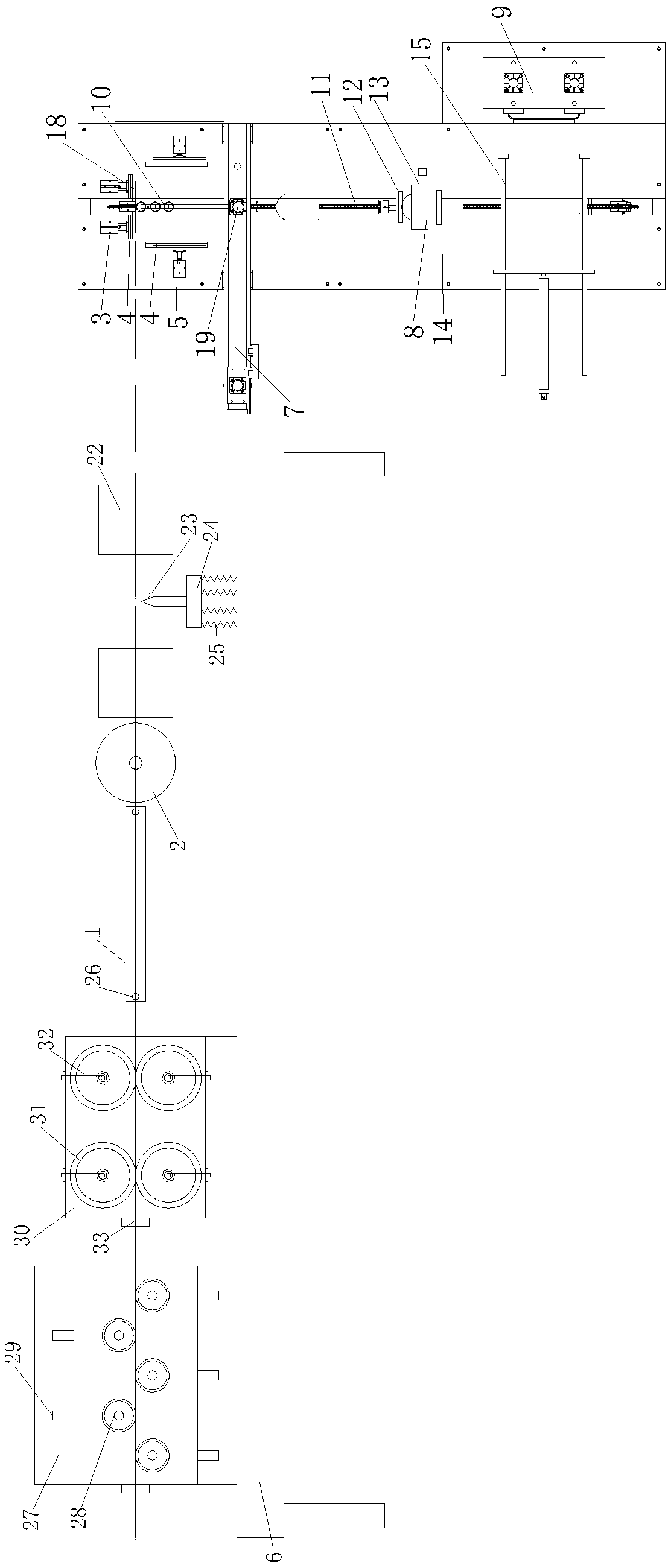
Automatic cutting and bending machine for alloy wire and machining technology thereof
An alloy wire and bending machine technology, applied in metal processing, metal processing equipment, manufacturing tools, etc., can solve the problem that the bending point, the solid angle parameters of the bending are difficult to be consistent, and the symmetry and balance cannot meet the design requirements. , the parameters of the bending point are difficult to be consistent, etc., to improve the production qualification rate and assembly shape consistency, uniform force, and reduce labor intensity.
- Summary
- Abstract
- Description
- Claims
- Application Information
AI Technical Summary
Problems solved by technology
Method used
Image

Examples
Embodiment Construction
[0028] The specific embodiments of the present invention will be further described below in conjunction with the accompanying drawings. It should be noted here that the descriptions of these embodiments are used to help understand the present invention, but are not intended to limit the present invention. In addition, the technical features involved in the various embodiments of the present invention described below may be combined with each other as long as they do not constitute a conflict with each other.
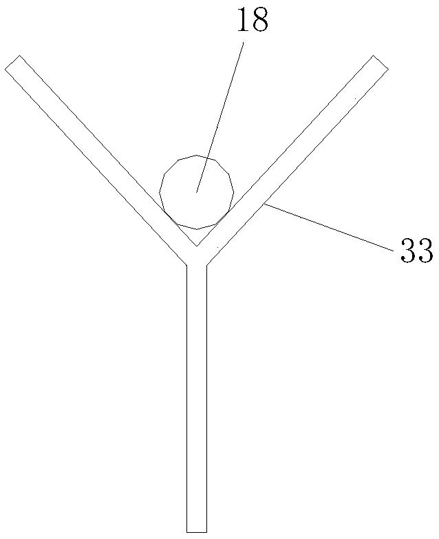
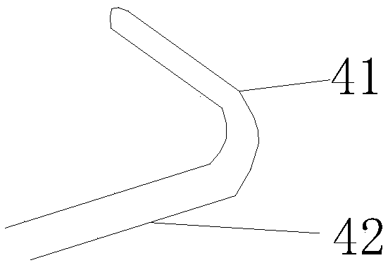
[0029] refer tofigure 1 , figure 2 , image 3 , Figure 4 and Figure 5 Shown is a structural schematic diagram of an automatic cutting and bending machine for alloy wire and its processing technology, a structural schematic diagram of a Y-shaped positioning bracket, a structural schematic diagram of a finished product, a perspective view of a bending equipment, and a structural schematic diagram of a flange positioning block. An automatic cutting and bending machin...
PUM
 Abstract
Description
Claims
Application Information
 - R&D Engineer
- R&D Manager
- IP Professional
- Industry Leading Data Capabilities
- Powerful AI technology
- Patent DNA Extraction
Browse by: Latest US Patents, China's latest patents, Technical Efficacy Thesaurus, Application Domain, Technology Topic, Popular Technical Reports.
© 2024 PatSnap. All rights reserved.Legal|Privacy policy|Modern Slavery Act Transparency Statement|Sitemap|About US| Contact US: help@patsnap.com