Technology and system for capturing and preserving carbon dioxide with low energy

A carbon dioxide and low energy consumption technology, applied in the field of high efficiency and low energy consumption flue gas carbon dioxide capture and storage system, can solve the problems of reducing initial investment cost, high energy consumption, and low efficiency, so as to reduce investment cost, improve efficiency, reduce The effect of power consumption

Active Publication Date: 2019-01-11
INST OF ENGINEERING THERMOPHYSICS - CHINESE ACAD OF SCI +1
View PDF15 Cites 10 Cited by
  • Summary
  • Abstract
  • Description
  • Claims
  • Application Information

AI Technical Summary

Problems solved by technology

[0006] In view of the disadvantages and deficiencies of the existing post-combustion carbon dioxide capture technology, such as high energy consumption, low efficiency, and large investment, the present invention aims to provide a high-efficiency and low-energy consumption flue gas carbon dioxide capture and storage system. Based on the principle of high-pressure liquefaction and separation, the system combines flue gas compression with recovery of expansion work and recovery of waste heat from the regenerator to save power consumption to the greatest extent; at the same time, by combining with energy storage and heat storage systems, it plays the function of peak regulation in power plants , to achieve multiple uses of one input, and reduce the initial investment cost of the unit; in addition, the system can also provide the cold source required for the removal of carbon dioxide at low temperature, further reducing power consumption and improving efficiency

Method used


Image

  • Technology and system for capturing and preserving carbon dioxide with low energy
  • Technology and system for capturing and preserving carbon dioxide with low energy
  • Technology and system for capturing and preserving carbon dioxide with low energy

Examples


Embodiment 1

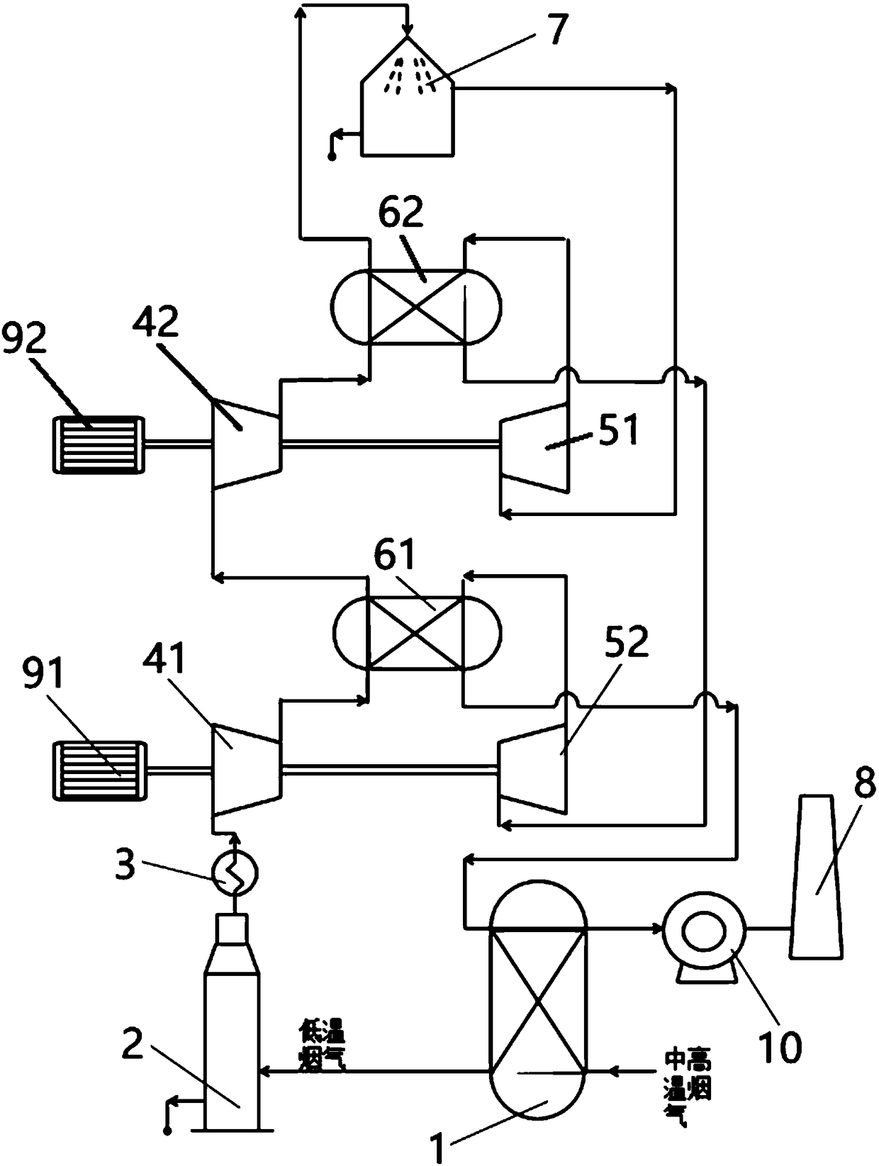
[0032] figure 1 It is the schematic diagram of embodiment 1. Such as figure 1 As shown, the low-energy carbon dioxide capture and storage system of the present invention includes a heat recovery heat exchanger 1, a desulfurization and denitrification tower 2, a dryer 3, a compressor unit, an expansion unit, interstage cold regenerators 61, 62, gas-liquid Separation device 7, chimney 8, drive motor 91,92, blower fan 10. Wherein, the compressor unit includes two-stage compressors 41, 42, and the exhaust port and the air inlet of adjacent two-stage compressors 41, 42 are connected through pipelines, and the exhaust pipes of each stage compressor 41, 42 There are one-stage intercooler regenerators 61 and 62 on the road, and the exhaust gases of the compressors 41 and 42 at each stage pass through the hot sides of the corresponding intercooler regenerators 61 and 62 to release heat. The expansion unit includes two-stage expanders 51, 52, the exhaust port and the intake port of t...

Embodiment 2

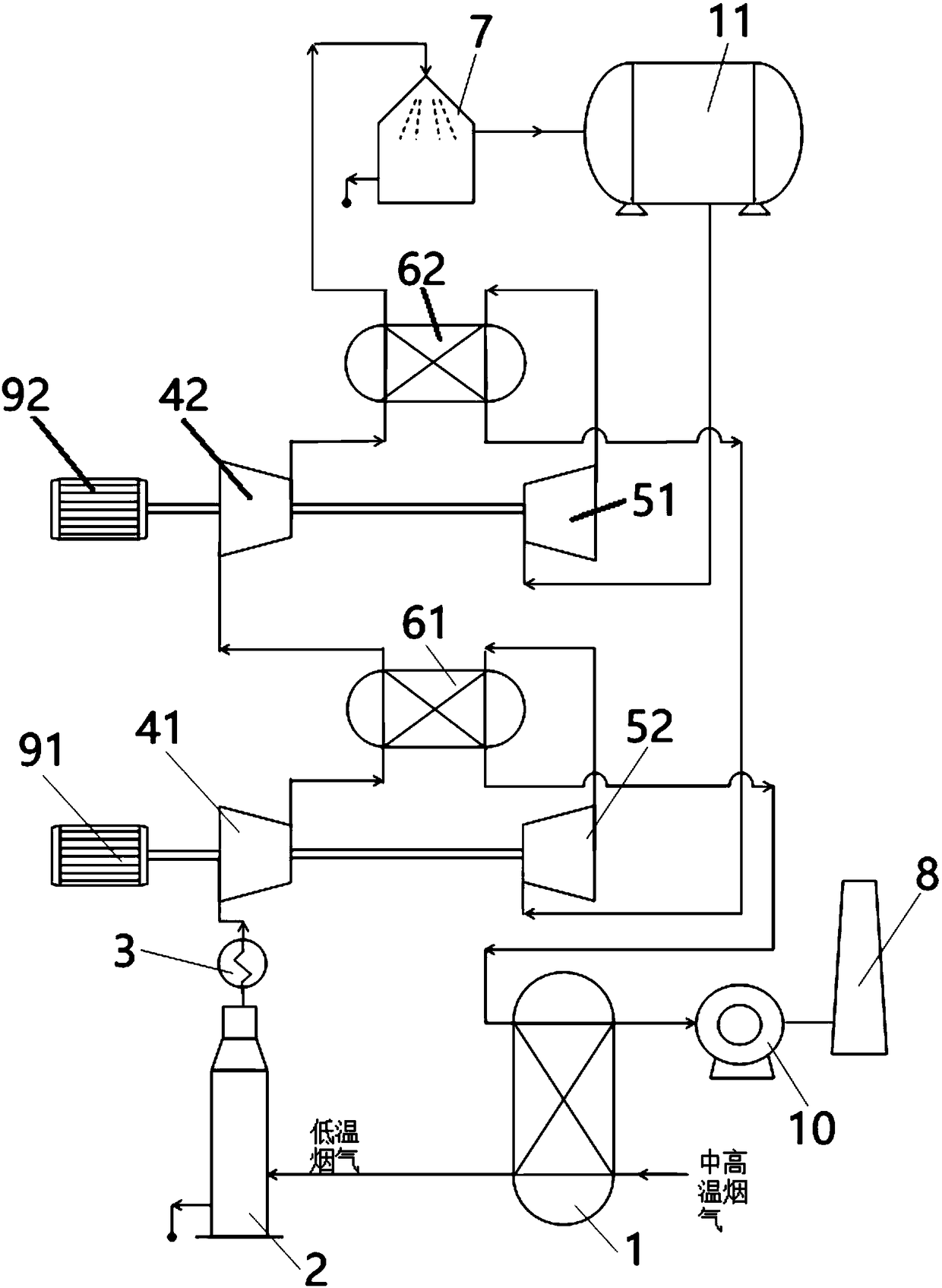
[0036] figure 2 It is the schematic diagram of embodiment 2. The difference from Embodiment 1 is that a compressed gas storage tank 11 is arranged on the communication pipeline between the high-pressure gas outlet of the gas-liquid separation device 7 and the air inlet of the first-stage expander 51, and each intercooler 61, 62 is a heat storage type intercooler. The high-pressure gas from which carbon dioxide has been removed can be temporarily stored in the compressed gas storage tank 11 to form an energy storage system. When the power is surplus at night, the drive motor is used to compress the flue gas and store the high-pressure gas. During the day, the high-pressure gas is released to drive the expander to replace the drive. The motor compresses the flue gas, or is used to drive other power and power generation equipment to play a role in peak regulation. For systems with compressed gas storage tanks, cold air cannot be supplied at any time after expansion, and the in...

Embodiment 3

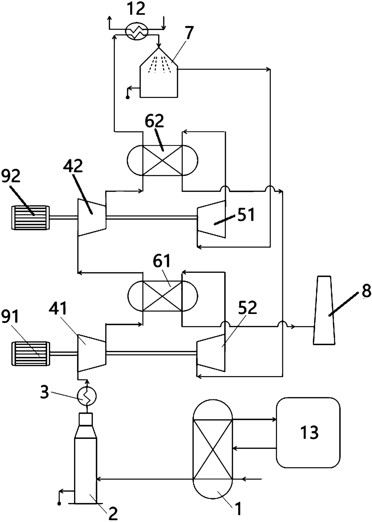
[0038] image 3 It is the schematic diagram of embodiment 3. Different from Embodiment 1, a water-cooled heat exchanger 12 is provided on the inlet pipeline of the gas-liquid separation device 7, and the exhaust port of the last stage expander 52 passes through the cold side of the first interstage cold regenerator 61 and then connects with the The flue gas discharge tower 8 is connected, and the cold side of the heat recovery heat exchanger 1 is connected with an absorption chiller 13 , and the cold water produced by the absorption chiller 13 is passed into the cold side of the water-cooled heat exchanger 12 . For natural gas boilers, boilers operating in summer, etc., the flue gas can be discharged at low temperature, so it is not necessary to reheat before discharge. After entering the water-cooled heat exchanger 12, it is used to further cool the high-pressure flue gas passed into the gas-liquid separation device 7, so as to improve the carbon dioxide capture effect. The...


PUM


Abstract

The invention relates to a system for capturing and preserving carbon dioxide with a low energy. Medium-high temperature flue gas generated by a coal-fired power plant is introduced into a heat recovery heat exchanger to release high-temperature waste heat and become low-temperature flue gas, the low-temperature flue gas is subjected to desulfurization and denitrification treatment, and then enters a compressor unit, the obtained compressed flue gas is cooled by indirect cooling heat regenerators, and then enters a gas-liquid separator to separate liquid carbon dioxide in the flue gas, carbondioxide removed high-pressure gas sequentially enters the cold sides of all-stage indirect-cooling heat regenerators and expansion units to do work, the gas obtained after the expansion work undergoesheat recovery by the heat recovery heat exchanger to reach a discharge temperature, and the obtained gas is conveyed into a chimney, and then is discharged to atmosphere. The system combines flue gascompression with expansion work recovery and the waste heat recovery of the heat regenerator, so the power is maximally saved; the system is combined with an energy storage and heat storage system toachieve peak regulation of the power plant, so the initial investment cost per unit is reduced; and the system also provides the cold source needed by low-temperature removal of carbon dioxide in order to reduce the power consumption, so the efficiency is increased.

Description

technical field [0001] The invention belongs to the technical field of coal-fired power plant flue gas carbon dioxide capture and power plant energy saving and consumption reduction, and relates to a carbon dioxide capture and storage system, and more specifically relates to a high-efficiency and low-energy consumption flue gas carbon dioxide capture and storage system system. Background technique [0002] The existing carbon capture and storage methods are mainly divided into: pre-combustion capture, oxyfuel combustion capture and post-combustion capture. Pre-combustion capture technology is a carbon capture method that separates carbon dioxide from high-carbon fossil fuels before their combustion. Typical systems such as integrated coal gasification combined cycle, the process of separating carbon dioxide is mainly divided into two steps: 1) high-carbon fossil energy Convert into hydrogen and carbon dioxide in an environment with sufficient oxygen; 2) Separate hydrogen an...

Claims


Application Information

Patent Timeline
Patent Type & Authority Applications(China)
IPC IPC(8): B01D53/00
CPCB01D53/00B01D2257/504Y02C20/40
Inventor 姜玉雁梁世强胡和敏郭朝红岳鹏郭永献曾秒
Owner INST OF ENGINEERING THERMOPHYSICS - CHINESE ACAD OF SCI
Why Eureka
Try Eureka