
Dust removal device used for factory processing workshop based on electrostatic dust removal technology

A technology for electrostatic dust removal and processing workshops, which is applied in the fields of combination devices, dispersed particle separation, chemical instruments and methods, etc., can solve the problems of insignificant processing dust treatment effect of floating dust, etc., and achieve the effect of preventing floating dust from accumulating.

Inactive Publication Date: 2019-01-11
渠学利
View PDF7 Cites 1 Cited by
  • Summary
  • Abstract
  • Description
  • Claims
  • Application Information

AI Technical Summary

Problems solved by technology

The improvement of the air in the existing processing workshop is to install a fan to directly exchange with the outdoor air, thereby improving the air quality. However, this method has no obvious effect on the treatment of floating dust and processing dust in the air of the workshop. Therefore, needs further improvement

Method used


Image

  • Dust removal device used for factory processing workshop based on electrostatic dust removal technology
  • Dust removal device used for factory processing workshop based on electrostatic dust removal technology
  • Dust removal device used for factory processing workshop based on electrostatic dust removal technology

Examples


Embodiment 1

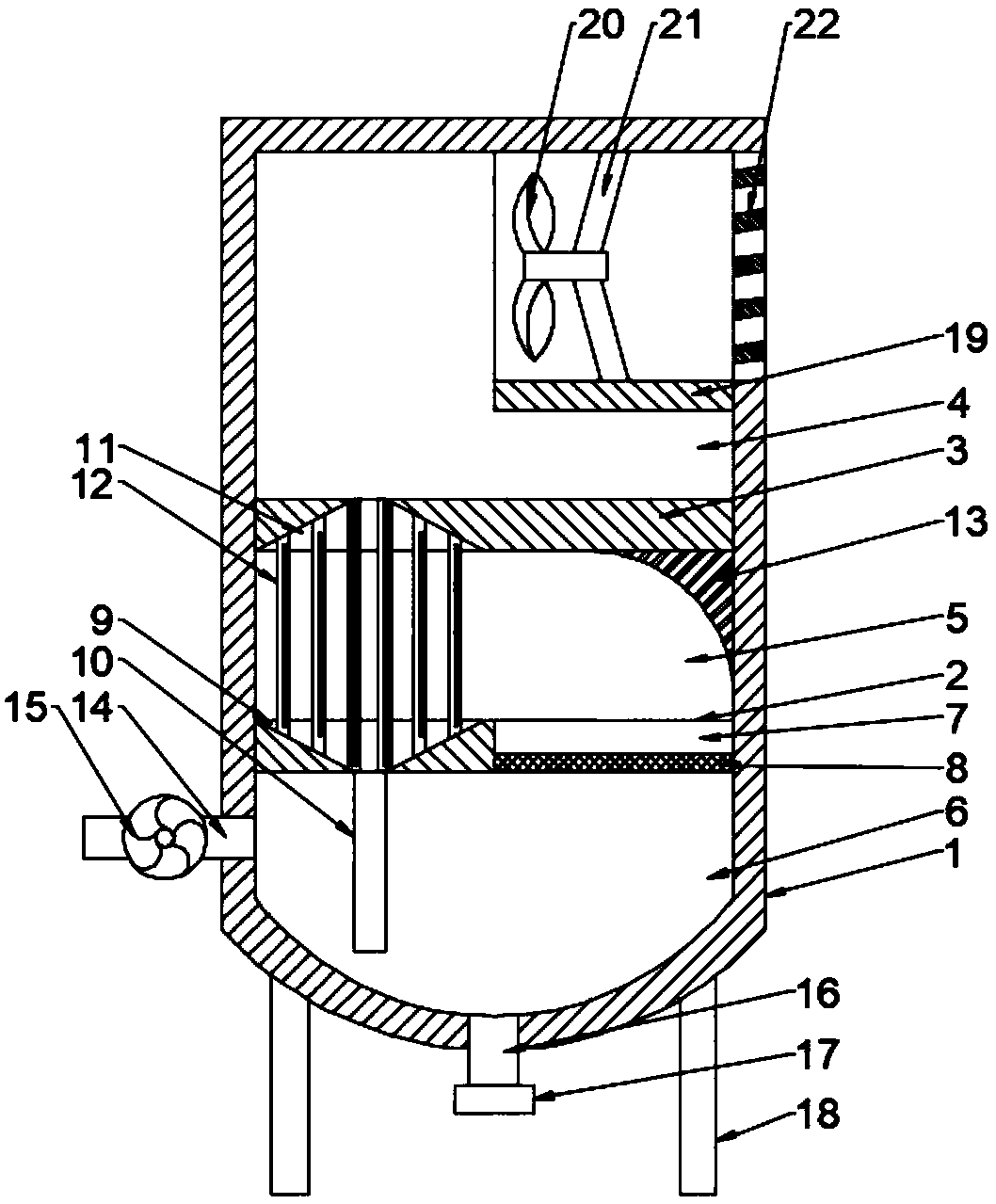
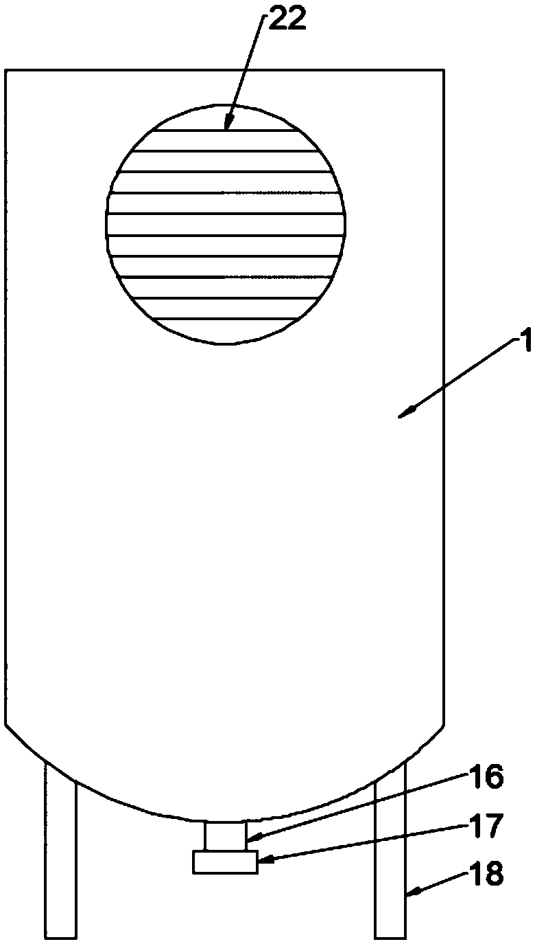
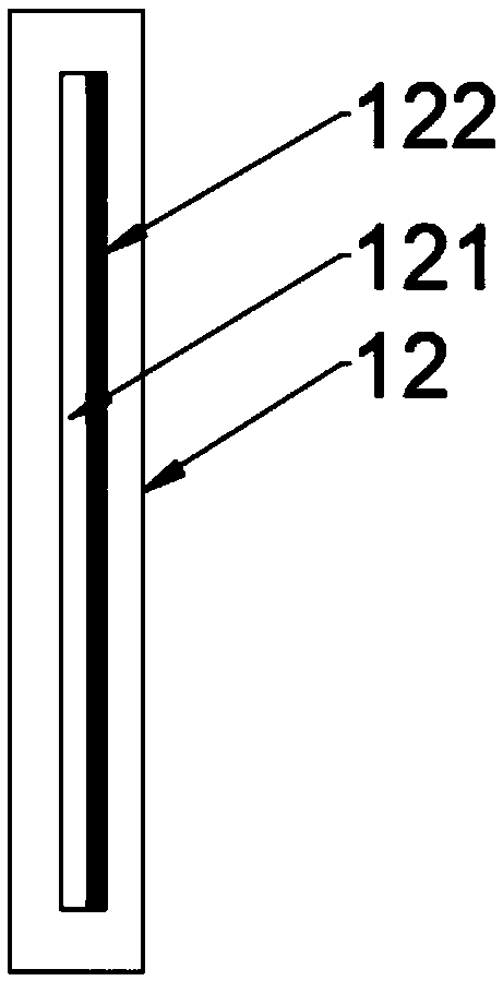
[0027] see Figure 1~3 , a dust removal device for factory processing workshops based on electrostatic dust removal technology, comprising a body 1, an upper partition 3 and a lower partition 2 are provided at the bottom of the inner cavity of the body 1, and the upper partition 3 is arranged on the lower partition 2 Above, the upper partition 3 and the lower partition 2 divide the inner chamber of the body 1 into an exhaust chamber 4, a dust removal chamber 5 and an air intake chamber 6 in sequence from top to bottom, and the external air first enters the air intake chamber 6, Then enter the dust removal chamber 5 through the air intake chamber 6, carry out the dust removal work in the dust removal chamber 5, and finally enter the exhaust chamber 4 to be discharged.

[0028] The left side of the upper partition 3 is provided with an air outlet 11, and the air outlet 11 is a tapered hole, and the lower partition 2 is provided with a dust discharge hole 9 and a communication ho...

Embodiment 2

[0030] This embodiment is a further elaboration on the basis of Embodiment 1. A dust filter 8 is provided in the communicating hole 7, and the air is initially filtered through the dust filter 8, and the large particles of floating dust in the air are directly removed. Floating dust directly falls on the bottom wall of the air intake cavity 6 .

[0031] The top of the right end of the dust removal chamber 5 is provided with a deflector 13 matched with the communication hole 7, so that the air from the communication hole 7 moves to the left under the action of the deflector 13 and enters between the dust collecting plate 12. room, which is convenient for electrostatic dust removal of the air.

[0032] The top of the left end of the air intake chamber 6 is connected to the air intake pipe 14, the air intake pipe 14 is provided with a blower fan 15, and under the action of the blower fan 15, outside air is pulled into the air intake chamber 6 through the air intake pipe 14; The ...

Embodiment 3

[0034] This embodiment is a further elaboration on the basis of Embodiment 1. The top of the right side of the air outlet chamber 4 is connected to the air outlet pipe 19, and the opening of the outer side of the air outlet pipe 19 is provided with a shutter 22. The left side of the inner cavity is provided with an exhaust fan 20, and the exhaust fan 20 is fixedly connected to the inner cavity wall of the air outlet pipe 19 through the connecting rod 21, and the exhaust fan 20 is started to draw the filtered air in the exhaust chamber 4 to pass through the air outlet pipe. 19 discharge.

[0035] The working principle of embodiment 1-3, under the effect of blower fan 15, pulls outside air to enter air intake cavity 6 through intake pipe 14, then enters dust removal cavity 5 through communication hole 7, and air realizes cleaning through dust filter net 8 in communication hole 7. The air is preliminarily filtered to directly remove large particles of floating dust in the air, an...


PUM


Abstract

The invention discloses a dust removal device used for a factory processing workshop based on an electrostatic dust removal technology. The device comprises a device body, the bottom of an inner cavity of the device body is provided with an upper separator plate and a lower separator plate, and the upper separator plate and the lower separator plate divide the inner cavity of the device body intoa discharge chamber, a dust removal chamber and an air inlet chamber from top to bottom, the left side of the upper separator plate is provided with an air outlet hole, and the lower separator plate is provided with a dust exhaust hole and a communication hole, and the bottom end of the dust exhaust hole is connected with a communication tube matched with the air inlet chamber, a plurality of dustcollecting plates are evenly arranged between the dust exhaust hole and the air outlet hole, and a dust collecting pole is arranged on the dust collecting plate. The device realizes the preliminary filtration of the air through a filter screen, and removes the large particle floating dust in the air; the dust charge in the gas is separated from the air flow under effect of the electric field by the dust collecting plate, and the work of dust removal is realized, the dust after dust removal falls directly into the dust exhaust hole, and then falls into the air intake chamber through the communication tube, and dust removal to the air is realized. At the same time, the dust particles are also discharged in time to prevent the accumulation of floating dust which can affect the practical lifeof the device.

Description

technical field [0001] The invention relates to the field of dust removal equipment, in particular to a dust removal device for factory processing workshops based on electrostatic dust removal technology. Background technique [0002] A factory, also known as a manufacturing plant, is a type of large industrial building used to produce goods. Most factories have a production line consisting of large machines or equipment. In the modern history of the world, it generally refers to the large-scale production of capitalist machines, that is, capitalist industrial sites that use mechanized labor instead of manual labor. From the 18th to the 19th century, after the industrial revolution, machines were widely used in production, which laid a solid material and technical foundation for the capitalist production mode. With the help of mechanized mass production, the capitalist economy finally defeated the feudal economy and petty commodity economy and established its dominant posi...

Claims


Application Information

Patent Timeline
IPC IPC(8): B01D50/00
CPCB01D50/00
Inventor 渠学利
Owner 渠学利
Learn More