
Photoelectric detection device, system and method

A photoelectric detection and optoelectronic technology, applied in the field of photoelectric detection, can solve the problems of inability to measure, poor signal-to-noise ratio, incompatibility of single-chip FPGA, etc. and processing speed effects

Active Publication Date: 2019-01-08
BEIJING NORMAL UNIVERSITY
View PDF3 Cites 3 Cited by
  • Summary
  • Abstract
  • Description
  • Claims
  • Application Information

AI Technical Summary

Problems solved by technology

[0004] Document 1 (Santangelo M F, La Cono S, Vasquez P, et al.CY5fluorescencemeasured with silicon photomultipliers, 2014[C].IEEE.) reported the use of a silicon photomultiplier (SiPM) to detect the concentration of Cy5 fluorescent dyes, through current integration The mode calculates the difference between photocurrent and dark current to obtain the concentration of Cy5 solution, but the signal-to-noise ratio of weak light measured by current integration mode is not as high as that of photon counting method, so weaker fluorescent signals cannot be measured
[0005] Document 2 (Mik L, Kucewicz W, Barszcz J, et al.Silicon photomultiplier asfluorescence light detector, MIXDES 2011, 18th International Conference "MixedDesign of Integrated Circuits and Systems", June 16-18, 2011, Gliwice, Poland) introduced The method of collecting fluorescence signals based on SiPM trigger gating and photon counting method can measure 60pg / ml to 1μg / ml fluorescein solution. The photon counting method used is the traditional measurement of the total number of photoelectrons per unit time, but its The disadvantage is that it cannot remove the associated noise such as optical crosstalk and post-pulse of SiPM, resulting in poor signal-to-noise ratio and low detection sensitivity
In addition, this measurement method needs to count the charge information of the pulse, and then make a statistical distribution, which is incompatible with a single-chip FPGA, making the readout circuit complex in structure and large in size

Method used


Image

  • Photoelectric detection device, system and method
  • Photoelectric detection device, system and method
  • Photoelectric detection device, system and method

Examples


Embodiment Construction

[0041] Embodiments of the present invention will be described below with reference to the drawings. In the description and drawings, specific embodiments of the invention are disclosed in detail, indicating the manner in which the principles of the invention may be employed. It should be understood that the invention is not thereby limited in scope. The invention embraces many changes, modifications and equivalents within the spirit and scope of the appended claims.

[0042] It should be noted that representation and description of components and processes that are not related to the present invention and known to those of ordinary skill in the art are omitted from the drawings and descriptions for the purpose of clarity.

[0043] Features described and / or illustrated with respect to one embodiment can be used in the same or similar manner in one or more other embodiments, in combination with, or instead of features in other embodiments .

[0044] It should be emphasized th...


PUM


Abstract

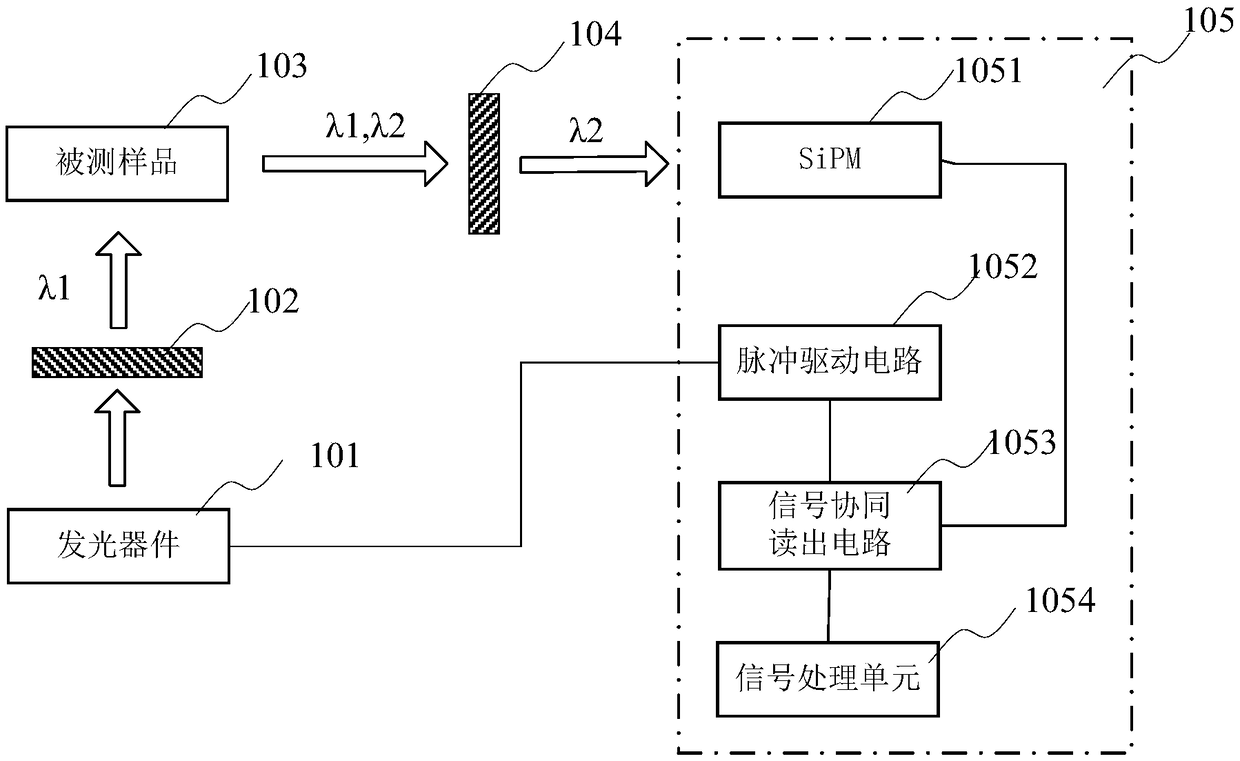
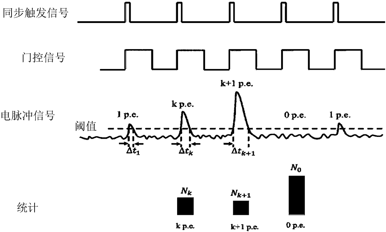
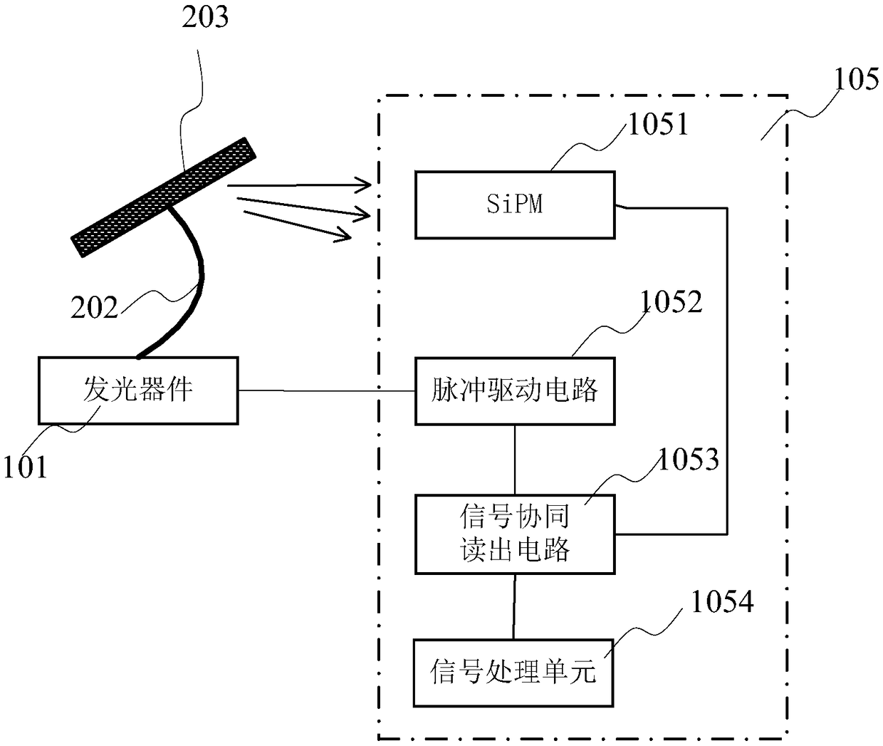
The invention relates to a photoelectric detection device, system and method. The photoelectric detection device comprises a silicon photomultiplier, a signal cooperative reading circuit and a signalprocessing unit, wherein the silicon photomultiplier is used for detecting optical pulse signals from a detected sample after the detected sample is irradiated by optical pulse and converting the detected signals into electrical pulse signals; the signal cooperative reading circuit is connected with the silicon photomultiplier and used for cooperatively generating gate control signals for controlling output of the silicon photomultiplier on the basis of pulse control signals which are used for controlling a light emitting device to generate the optical pulse signals, so that the silicon photomultiplier is in a gate control photon counting mode, and the electrical pulse signals output by the silicon photomultiplier are collected in gate control time of the gate control signals; the signal processing unit is connected with the signal cooperative reading circuit and used for counting photoelectron events on the basis of photoelectron number corresponding to each pulse in the collected electrical pulse signals, and when a photoelectron event counting result meets Poisson distribution conditions, the average photoelectron number is calculated on the basis of the counted photoelectron number according to a probability function of Poisson distribution.

Description

technical field [0001] The present invention relates to the technical field of photoelectric detection, in particular to the detection of weak light signals, in particular to a photoelectric detection device, system and method. Background technique [0002] Photoelectric detection technology is widely used in scientific research, biomedicine and industrial production, among which bioluminescent detection has a very important application in the medical field. Fluorescence is a photoluminescence phenomenon. In medical research, certain biomolecules can be marked with specific fluorescent probes, and the content of biomolecules can be obtained by detecting the intensity of fluorescent signals. Real-time fluorescence quantitative PCR technology uses fluorescent probes to label DNA molecules. The fluorescence intensity is linearly related to the concentration of DNA molecules, and the fluorescence signal is relatively weak. By monitoring the changes in fluorescence intensity in ...

Claims


Application Information

Patent Timeline
IPC IPC(8): G01N27/00G01N21/84G01N21/01
CPCG01N21/01G01N21/84G01N27/00G01N2021/0112
Inventor 韩德俊刘健代雷
Owner BEIJING NORMAL UNIVERSITY
Learn More