
Separable vacuum interconnected system

An interconnection system and separate technology, applied in the field of vacuum interconnection instruments, can solve the problems of increased transmission burden, the danger of trolley derailment, large footprint of vacuum interconnection devices, and inflexibility of large interconnection devices, so as to achieve interconnection and compatibility. Enhanced networking and convenience, less demand for interior space and load-bearing

Active Publication Date: 2019-01-08
UNIV OF SCI & TECH OF CHINA
View PDF18 Cites 7 Cited by
  • Summary
  • Abstract
  • Description
  • Claims
  • Application Information

AI Technical Summary

Problems solved by technology

[0003] In the existing vacuum interconnection equipment, there are the following problems: 1. The vacuum interconnection device occupies a large area. In order to cooperate with the interconnection between devices, a laboratory or factory building with a large span is required to support it; 2. The large interconnection device is not flexible enough: especially the device that uses a linear transmission trolley to transmit samples, the one-way movement of the trolley will greatly reduce the efficiency of sample transmission, especially when two devices that need to be interconnected are placed far away, so It will greatly reduce the efficiency of sample transfer, and at the same time, the transmission burden will also increase the risk of derailment of the trolley, causing the entire sample transfer pipeline to stop working

Method used


Image

  • Separable vacuum interconnected system
  • Separable vacuum interconnected system
  • Separable vacuum interconnected system

Examples


Embodiment Construction

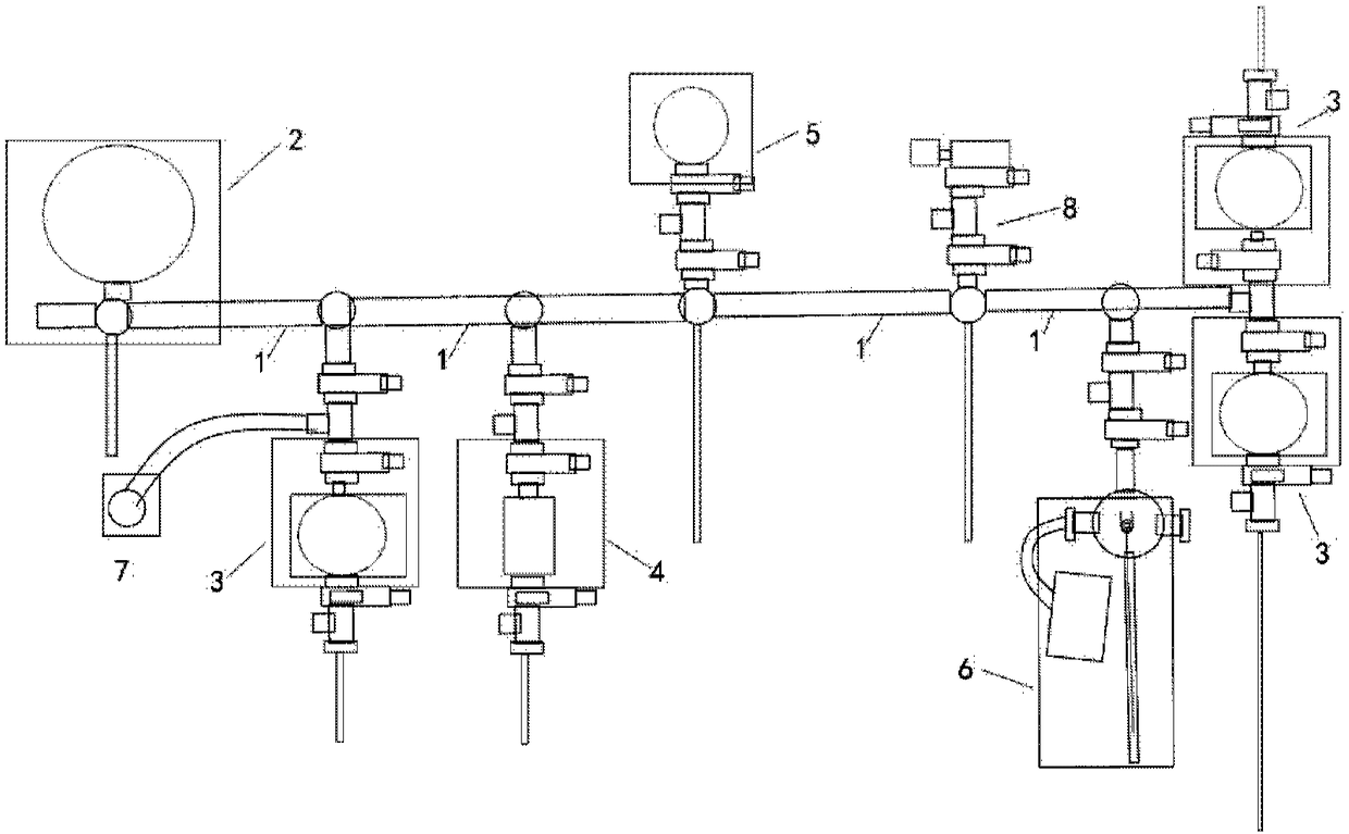
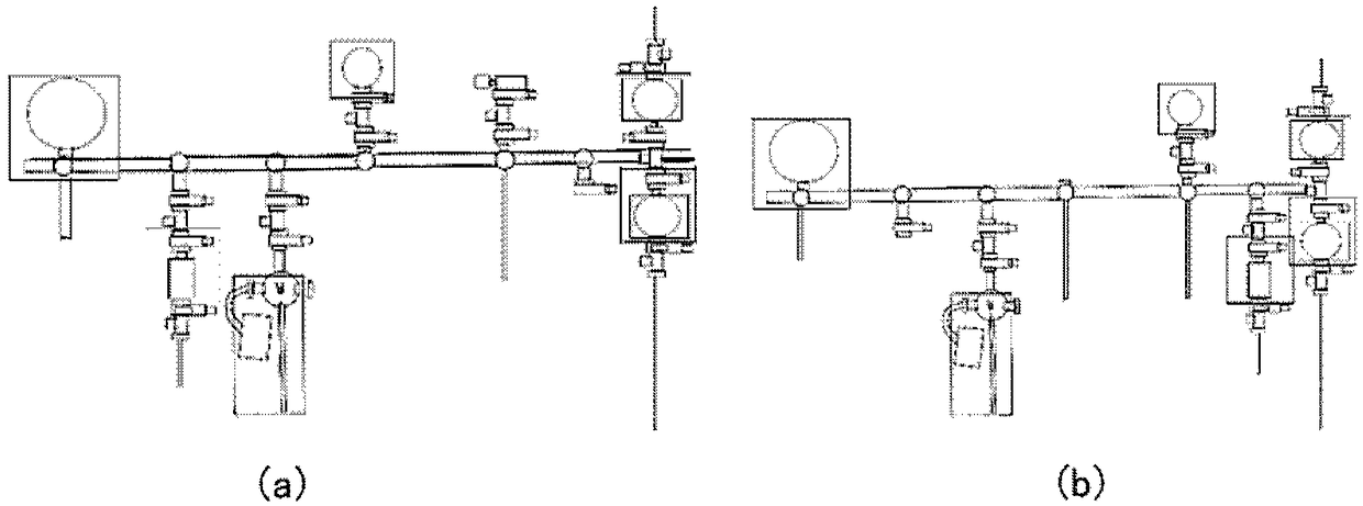
[0065] The present disclosure provides a detachable vacuum interconnection system, which includes: a main interconnection pipeline, a main interconnection device, a plurality of movable split devices, and an integrated constant temperature platform, and a plurality of movable The split device can be connected and disassembled on the main interconnection pipeline, and can be connected and separated from the main interconnection fixing device. At the same time, multiple split devices can be used alone or in any combination to form an integrated cavity. The equipment for material growth, testing and sample transfer can be adjusted according to the needs of the experiment and the spatial distribution of the site. It is flexible and convenient, and each split device has a small footprint and has a small demand for indoor space and load-bearing. Better security; and realize in-situ sample transfer, long-distance transportation of samples at a specific temperature and cross-border tra...


PUM


Abstract

The invention discloses a separable vacuum interconnected system. The separable vacuum interconnected system comprises a main interconnected pipeline, a main interconnected fixing device, multiple movable separated devices and an integrated constant temperature platform, wherein the main interconnected fixing device is arranged on the main interconnected pipeline; the multiple movable separated devices comprise movable high vacuum growing equipment, mobile non-high-vacuum growing equipment, mobile vacuum measuring equipment, a vacuum constant temperature sample transmission trolley and a mobile vacuum pump truck system, wherein the movable separated devices can be connected to and detached from the main interconnected pipeline and can be combined with and separated from the main interconnected fixing device; and meanwhile, the multiple movable separated devices can be singly used or each two of the multiple movable separated devices are combined and connected at will to form an integrated chamber; and the integrated constant temperature platform is used for in-situ and constant temperature transmission of samples. The separable vacuum interconnected system, disclosed by the invention, has the advantages that the use is flexible and convenient, the floor space of each separated device is small, requirements on indoor space and load are smaller, and meanwhile, various pump body resources are sufficiently utilized by using the separated design, so that the cost of a vacuum interconnected device is greatly reduced.

Description

technical field [0001] The disclosure belongs to the field of vacuum interconnection instruments, and relates to a separable vacuum interconnection system. Background technique [0002] In recent years, with the improvement of sample growth technology and testing technology, more and more growth and testing characterizations rely on vacuum environment, especially high vacuum environment. The growth and measurement equipment currently used in high vacuum mainly include the following types: (1) Molecular Beam Epitaxy (MBE, Molecular Beam Epitaxy) and various evaporation equipment; (2) Magnetron sputtering equipment; (3) Laser-assisted deposition Equipment; (4) chemical vapor deposition; (5) atomic layer deposition, etc.; (6) equipment based on surface characterization, including: scanning tunneling microscope, atomic force microscope, X-ray photoelectron spectroscopy, etc.; (7) micro-nano and cryogenic equipment . Among these growth and measurement instruments and equipment,...

Claims


Application Information

Patent Timeline
IPC IPC(8): C23C14/56C23C16/44C30B25/08F04B41/06
CPCF04B41/06C23C14/56C23C16/4412C30B25/08
Inventor 张汇汪逸凡施至刚
Owner UNIV OF SCI & TECH OF CHINA
Learn More