
High-frequency front end circuit and communication device

A front-end circuit, high-frequency signal technology, used in high-frequency amplifiers, electrical components, radio frequency amplifiers, etc., can solve problems such as high cost and large-area front-end circuits, and achieve the effect of low price and miniaturization

Inactive Publication Date: 2019-01-04
MURATA MFG CO LTD
View PDF4 Cites 20 Cited by
  • Summary
  • Abstract
  • Description
  • Claims
  • Application Information

AI Technical Summary

Problems solved by technology

Therefore, there is a problem of increasing the area and cost of the front-end circuit of the mobile communication terminal.

Method used


Image

  • High-frequency front end circuit and communication device
  • High-frequency front end circuit and communication device
  • High-frequency front end circuit and communication device

Examples


Embodiment approach 1

[0051] [1.1 Circuit configuration of communication device]

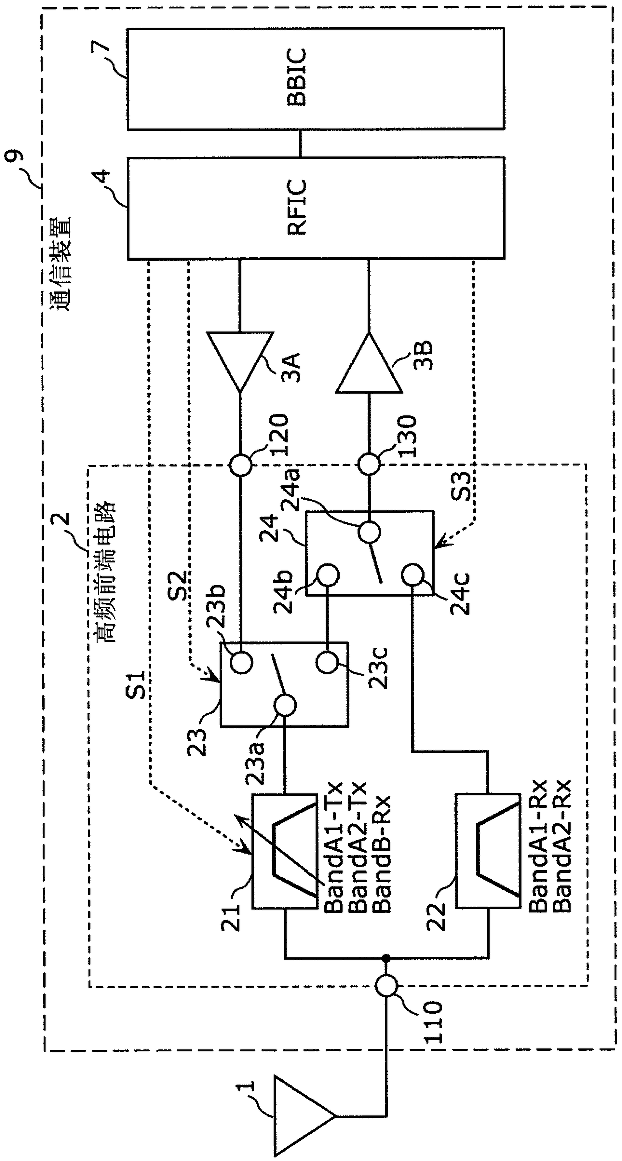
[0052] figure 1 It is a configuration diagram of the high-frequency front-end circuit 2 and its peripheral circuits according to the first embodiment. This figure shows an antenna element 1 , a high-frequency front-end circuit 2 , a transmission amplifier circuit 3A, a reception amplifier circuit 3B, an RF signal processing circuit (RFIC) 4 and a baseband signal processing circuit (BBIC) 7 . The high-frequency front-end circuit 2 , the transmission amplifier circuit 3A, the reception amplifier circuit 3B, the RF signal processing circuit (RFIC) 4 , and the baseband signal processing circuit (BBIC) 7 constitute a communication device 9 . The antenna element 1 , the high-frequency front-end circuit 2 , the transmission amplifier circuit 3A, the reception amplifier circuit 3B, and the RFIC 4 are arranged, for example, at the front end of a multi-mode / multi-band compatible mobile phone.

[0053] RFIC (Radio Frequency ...

Embodiment approach 2

[0143] Embodiment 1 exemplifies a high-frequency front-end circuit in which the pass band and the attenuation band are variable for the filter 21 and the pass band and the attenuation band are fixed for the filter 22 . On the other hand, in this embodiment, both filters are exemplified as high-frequency front-end circuits in which the pass band and the attenuation band are variable. Hereinafter, regarding the high-frequency front-end circuit according to the present embodiment, the description of the same points as those of the high-frequency front-end circuit according to the first embodiment will be omitted, and the different points will be mainly described.

[0144] [2.1 Circuit configuration of communication device]

[0145] Figure 11 It is a configuration diagram of the high-frequency front-end circuit 8 and its peripheral circuits according to the second embodiment. This figure shows an antenna element 1 , a high-frequency front-end circuit 8 , a transmission amplifie...


PUM


Abstract

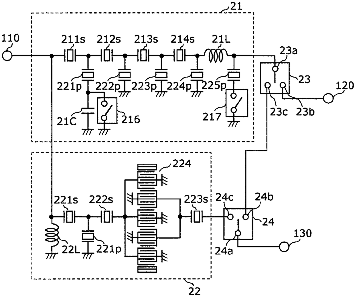
A high-frequency front end circuit (2) is provided with: a filter (21) provided with a first input / output terminal and a second input / output terminal, wherein the first input / output terminal is connected to an antenna common terminal (110), and a frequency of a passband is changed to that of a first passband or a second passband; a filter (22) provided with a third input / output terminal and a fourth input / output terminal, wherein the third input / output terminal is connected to the antenna common terminal (110), and the passband has a third passband the frequency of which does not overlap thatof the first passband or the second passband; and a switch (23) provided with a common terminal (23a) and selection terminals (23b) and (23c), wherein the common terminal (23a) is connected to the second input / output terminal, the selection terminal (23b) is connected to a transmission-side path, the selection terminal (23c) is connected to a reception-side path, and switching is exclusively performed between a connection between the common terminal (23a) and the selection terminal (23b) and a connection between the common terminal (23a) and the selection terminal (23c).

Description

technical field [0001] The invention relates to a high-frequency front-end circuit and a communication device. Background technique [0002] Conventionally, high frequency front-end circuits for selectively passing high frequency signals of a plurality of frequency bands (bands) have been put into practical use in order to cope with multimode / multiband, etc. complexization of mobile communication devices. [0003] Figure 14 It is a circuit configuration diagram of a multi-band compatible mobile communication terminal capable of carrier aggregation described in Patent Document 1. The mobile communication terminal shown in this figure includes an antenna 611, an adjustable duplexer 600, SPDT switches 612 and 613, duplexers 614, 615A, 615B, and 616, a low-noise amplifier 630, a power amplifier 631, and an RF signal processing circuit 632. And baseband signal processing circuit 633. The tunable duplexer 600 is composed of an inductor and a variable capacitance element. An ar...

Claims


Application Information

Patent Timeline
Patent Type & Authority Applications(China)
IPC IPC(8): H04B1/50H03H9/72H04B1/00H04B1/44
CPCH03F3/19H03F3/245H03F2200/171H03F2200/294H03F2200/451H03H9/6436H03H9/6483H03H9/725H04B1/0057H03H9/72H04B1/00H04B1/44H04B1/50
Inventor 野阪浩司
Owner MURATA MFG CO LTD
Learn More