An optimization method for non-full-phase operation of DC receiving-end condensers

An optimization method and non-full-phase technology, which is applied in AC network circuits, reactive power adjustment/elimination/compensation, electrical components, etc., can solve the problem of not being able to identify the non-full-phase state of low reactive power down-regulation cameras

Active Publication Date: 2020-07-21
STATE GRID HUNAN ELECTRIC POWER +2
View PDF1 Cites 0 Cited by
  • Summary
  • Abstract
  • Description
  • Claims
  • Application Information

AI Technical Summary

Problems solved by technology

[0007] In order to solve the problem that the current DC receiving-end regulator modulation group cannot recognize the non-full-phase state of the low-reactive output down-regulating camera, the present invention provides an optimization method for the non-full-phase operation of the DC receiving-end regulator, including:

Method used


Image

  • An optimization method for non-full-phase operation of DC receiving-end condensers
  • An optimization method for non-full-phase operation of DC receiving-end condensers

Examples


Embodiment Construction

[0028] The specific implementation manners of the present invention will be further described in detail below in conjunction with the accompanying drawings and embodiments. The following examples are used to illustrate the present invention, but are not intended to limit the scope of the present invention.

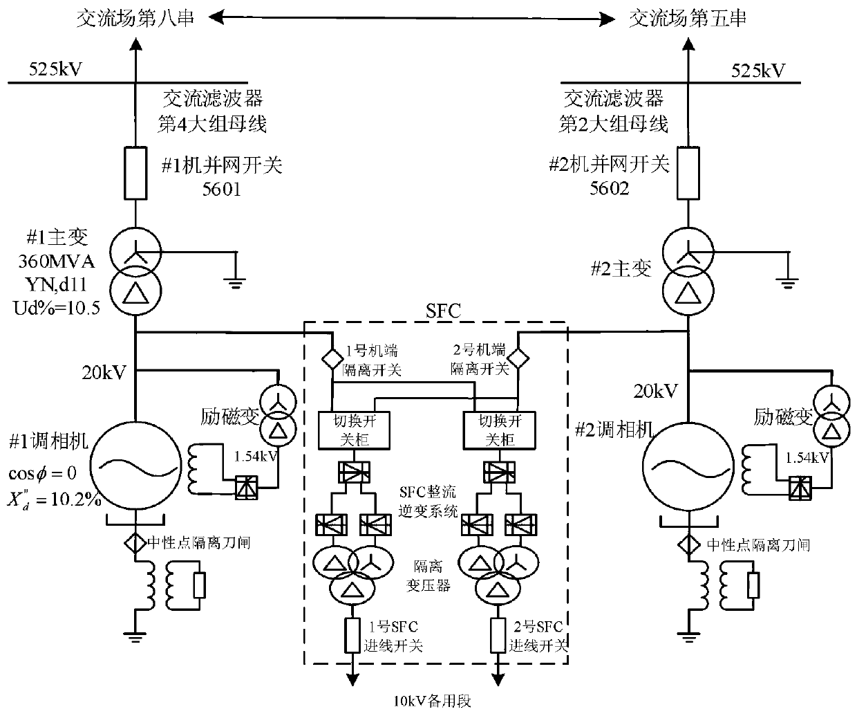
[0029] Xiangtan condenser is one of the first batch of 21 supporting condensers for UHV DC project. figure 2 According to a preferred embodiment of the present invention, it is the main wiring DC diagram of a DC receiver condenser, as shown in figure 2 As shown, the 10kV standby section leads to two outgoing lines for the SFC start-up circuit. The circuit is equipped with a 10kV circuit breaker on the busbar side of the 10kV standby section and the SFC incoming line side to avoid jumping the circuit breaker through long cables on both sides. The Xiangtan condenser group adopts the "converter-transformer" unit wiring method. The incoming lines of No. 1 and No. 2 main tra...


PUM


Abstract

The present invention provides a method for optimizing the non-full-phase operation of the DC receiver modulator, including: if the local non-full-phase signal is switched in and the current at the high-voltage side of the modulation unit and the main transformer does not reach the level of the modulation group non-full-phase Protection criterion conditions, send non-full-phase modulation reactive power command signal to the camera monitoring system; increase the reactive power output of the camera; if the reactive power output of the The non-full-phase protection has not yet acted, and the monitor system of the condenser will keep the condenser running with reactive power output that meets the criterion conditions of the non-full-phase protection of the modulation group. The present invention avoids the problem that the existing DC receiver-side regulator group has the non-full-phase state of the down-regulation camera due to the inability to recognize the low reactive power output, so that the controller continues to operate in the non-full-phase fault state, and prevents the controller from operating in the non-full-phase state. In the state of phase fault, the huge negative sequence current generated by the forced instantaneous output of a large amount of reactive power will cause huge damage to the rotor of the condenser and reduce the operating life of the condenser.

Description

technical field [0001] The invention relates to the DCS (distributed control system) technical field of a condenser transformer group, in particular to an optimization method for non-full-phase operation of a direct current receiver condenser. Background technique [0002] The condenser is generally used as a reactive power compensation device to adjust the reactive power of the power grid. Traditional condensers are generally rotating equipment, which have disadvantages such as large investment, high operating costs, complex structure, and difficult operation and maintenance of auxiliary systems. After the rapid development of power electronics technology, they were once replaced by static var compensation equipment such as SVC and STATCOM. [0003] In recent years, with the large-scale development of UHV DC transmission projects and the huge demand for temporary dynamic reactive power supporting capacity of the system in the "strong DC and weak AC" environment, the new gen...

Claims


Application Information

Patent Timeline
Patent Type & Authority Patents(China)
IPC IPC(8): H02J3/18
CPCH02J3/1885Y02E40/30
Inventor 徐浩朱维钧刘海峰潘伟梁文武李辉李刚臧欣刘宇余斌吴晋波郭思源洪权
Owner STATE GRID HUNAN ELECTRIC POWER
Why Eureka
Try Eureka