
Steering load simulator and steering system test method

A load simulation and steering system technology, which is applied in the direction of vehicle steering/bump performance, can solve the problems of difficult to guarantee the accuracy of the load simulation system and low service life, and achieve the effects of reliable data, improved service life, and favorable load force accuracy

Active Publication Date: 2020-12-25
TIANJIN TRINOVA AUTOMOTIVE TECH CO LTD
View PDF11 Cites 0 Cited by
  • Summary
  • Abstract
  • Description
  • Claims
  • Application Information

AI Technical Summary

Problems solved by technology

[0008] In view of this, the object of the present invention is to provide a steering load simulation device and a steering system test method to solve the problem that the accuracy of the steering system load simulation system in the prior art is difficult to guarantee, the service life is low, and the steering rocker arm and wheel side cannot be simulated. The technical problem of the impact of the assembly on the load of the steering system

Method used


Image

  • Steering load simulator and steering system test method
  • Steering load simulator and steering system test method
  • Steering load simulator and steering system test method

Examples


Embodiment 1

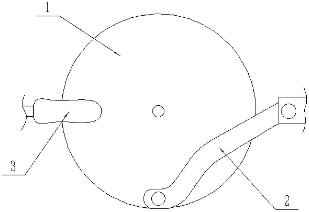
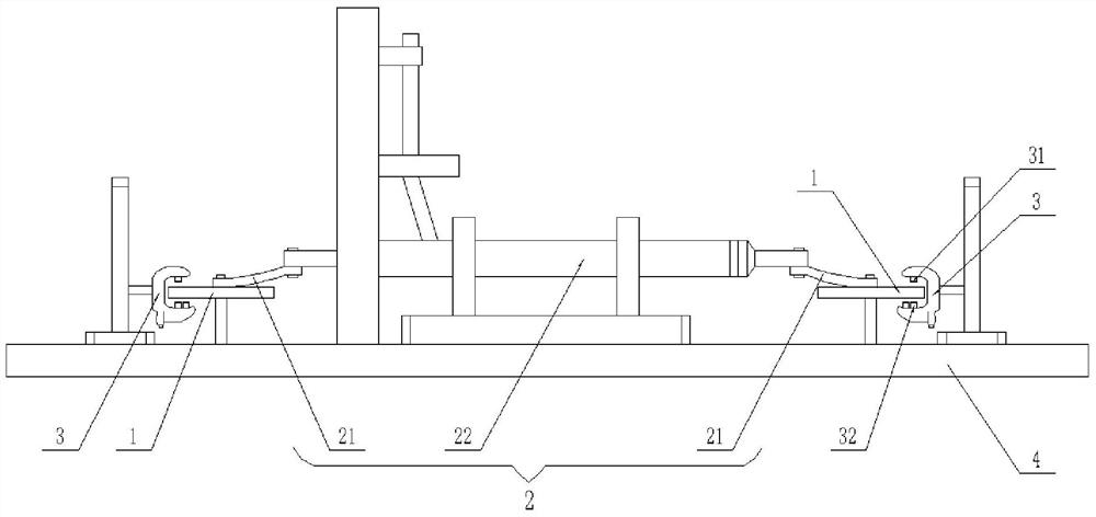
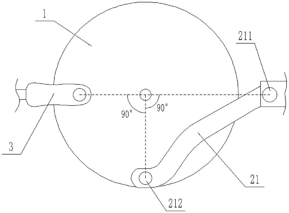
[0034] Such as figure 1 As shown, the steering load simulation device provided by the embodiment of the present invention includes: a linkage 1, a steering drive 2 and a brake 3, the steering drive 2 is used to drive the linkage 1 to move; the brake 3 is used to friction brake the linkage 1 , to hinder the movement of linkage 1.

[0035] Specifically, the linkage 1 is used to connect the steering system, and transmit the driving force of the steering system to the steering drive 2; the steering drive 2 moves relative to the brake 3 under the drive of the linkage 1, and the brake 3 is braked by friction. The brake 3 can adopt the electronic parking system, which replaces the hydraulic cylinder, hydraulic valve, hydraulic pump station and complex hydraulic circuit, greatly realizes the simplification of the system and avoids the exhaust during the system installation process. The problem of air bubbles can avoid system instability due to impurities mixed in the oil, and the sys...

Embodiment 2

[0048] The steering system test method provided in the embodiment of the present invention uses the steering load simulation device provided in Embodiment 1, and the steering system test method includes the following steps:

[0049] Calculate the theoretical value of the steering system load at the preset vehicle speed according to the preset vehicle speed;

[0050] Calculate the braking force of the brake 3 according to the theoretical value of the steering system load;

[0051] The control brake 3 loads the linkage 1 . Wherein, calculating the theoretical value of the steering system load at the preset vehicle speed according to the preset vehicle speed includes that the controller 5 inquires the theoretical value of the steering system load at the preset vehicle speed according to the preset vehicle speed, and the steering system load at each vehicle speed. Theoretical values ​​can be known through previous experiments and stored in the memory in advance for the controller...


PUM


Abstract

The invention provides a steering load simulation device and a steering system test method which relate to the technical field of vehicle steering tests. The steering load simulation device includes alinkage part, a steering drive part, and a brake. The steering drive part is used for driving the linkage part to move; and the brake is used for performing friction brake on the linkage part to stopmotion of the linkage part. The steering load simulation device of the invention solves the technical problem that in the prior art, a load simulation system of a steering system is difficult to guarantee the precision, is low in service life, and cannot simulate a steering rocker arm and a wheel side assembly to produce an effect on the load of the steering system.

Description

technical field [0001] The invention relates to the technical field of vehicle steering tests, in particular to a steering load simulation device and a steering system test method. Background technique [0002] The hydraulic steering loading system is a system that provides load to the steering mechanism based on hydraulic transmission. The hydraulic loading system is composed of rack and pinion steering gear, hydraulic cylinder, hydraulic valve, hydraulic pump station, sensor and so on. The hydraulic cylinder controls the speed and force according to the signal sent by the computer. The signal detected by the force sensor is compared with the command signal to realize signal feedback, and the flow of oil in the valve is controlled according to the feedback pressure, thereby controlling the movement of the hydraulic cylinder and realizing loading. [0003] The spring loading system can simulate the resistance when the car is turning and the returning force when returning to...

Claims


Application Information

Patent Timeline
Patent Type & Authority Patents(China)
IPC IPC(8): G01M17/06
CPCG01M17/06
Inventor 康雅文俞伟张璞林甲胜秦金喆
Owner TIANJIN TRINOVA AUTOMOTIVE TECH CO LTD
Learn More