
Installation structure of server sliding rail and server rack

A technology for installation structure and server, which is applied in the direction of rack/frame structure, server, support structure installation, etc. It can solve the problems that the installation operation needs to be improved, the installation operation is not simple and convenient, and the labor cost and working hours are high, so as to save manpower and working hours , Simple structure, fast and convenient assembly

Active Publication Date: 2022-01-11
GSLIDE
View PDF10 Cites 0 Cited by
  • Summary
  • Abstract
  • Description
  • Claims
  • Application Information

AI Technical Summary

Problems solved by technology

[0002] According to the prior art, the same applicant's Taiwan Province of China Invention No. I624235 "Front Bracket Quick Release Structure of Server Slide Rail" patent case discloses that the outer rail of the server slide rail is combined with the front bracket and The relevant technology of server rack installation is found to be practical after investigation. Only when it is intended to be installed, it is necessary to first move the paddle of the buckle and pivot it open by hand, so that the two fixing pins can be aligned and inserted. The server rack, so the installation operation is still not simple and convenient, and this structure includes the front bracket, base, toggle fastener, pivot assembly, buckle, paddle, outer sleeve, internal fixing pin, spring, torque There are many components such as springs, and the labor cost and working hours of assembly are relatively high
[0003] A second search of the same applicant's Taiwan Province of China Patent No. M582338 "Convenient Installation Structure for Server Slide Rails and Server Racks" also disclosed related technologies in which server slide rails are installed on server racks through fixed brackets. The inconvenient part is that before the installation operation, the rotary control part must be rotated open with one hand to align the two positioning posts with the corresponding two positioning holes of the server rack, so the installation work still needs to be improved

Method used


Image

  • Installation structure of server sliding rail and server rack
  • Installation structure of server sliding rail and server rack
  • Installation structure of server sliding rail and server rack

Examples


Embodiment Construction

[0040] The present invention will be described in further detail below in conjunction with the accompanying drawings, but it is not intended to limit the present invention.

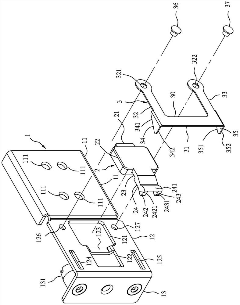
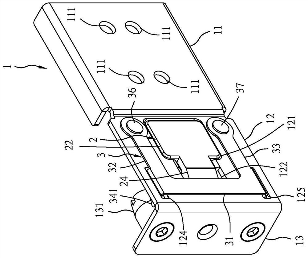
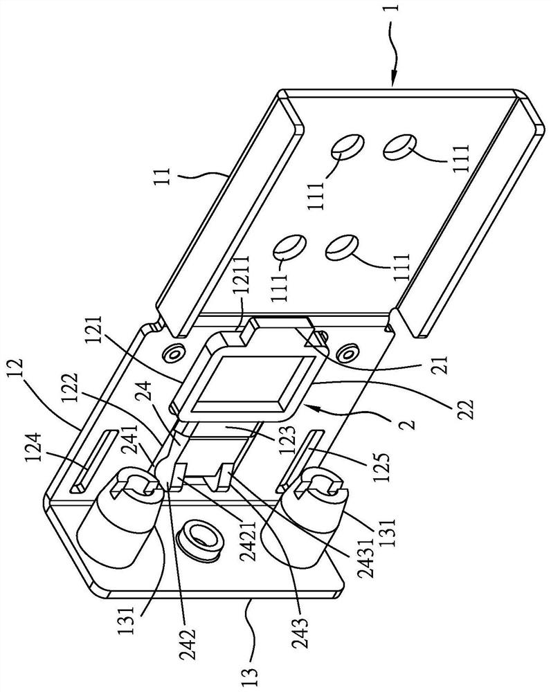
[0041] Such as Figure 1 to Figure 13 As shown, the installation structure of a server slide rail and a server rack in the present invention at least includes:

[0042] A fixed bracket 1 has a fixed part 11, the fixed part 11 is connected with one end of a connecting part 12, and the other end of the connecting part 12 is vertically connected with a mounting wall 13, and the mounting wall 13 is provided with at least two guide post 131, and the fixing part 11 is provided with a number of first positioning holes 111 to pass through a number of first locking components 112 (such as Figure 4 shown) and a server rail 4 (such as Figure 4 Shown) one end of the outer rail 41 is combined and fixed, and the server slide rail 4 is installed on a server rack 5 through the fixing bracket 1 (such as Figure 6 sho...


PUM


Abstract

An installation structure of a server sliding rail and a server rack at least comprises a fixing support, an elastic positioning block and a positioning elastic piece, when the server sliding rail is to be installed on the server rack, any component does not need to be rotated or pulled open by hands, two guide columns of the fixing support can be directly aligned with two fixing holes of the server rack to be inserted, then the first guide arm and the second guide arm can be naturally pushed away along the guidance of the first inclined parts of the first guide arm and the second guide arm of the positioning elastic piece along with the action in the insertion direction, and then the clamping parts of the first guide arm and the second guide arm are respectively clamped on the adjacent inner wall surfaces of the fixing hole of the server rack through elastic recovery force, so that the installation is completed; and when the server rack needs to be detached, the pressing part of the elastic piece positioning block is pressed by a hand, the clamping parts of the first guide arm and the second guide arm of the positioning elastic piece can be linked by the linkage part of the elastic piece positioning block to be separated from the server rack, and the server sliding rail is reversely pulled away from the server rack. The elastic sheet is linked and positioned through the elastic sheet positioning block, therefore, damage caused by elastic fatigue of the positioning elastic piece due to excessive force application can be avoided; and the installation structure is convenient and rapid to assemble due to simple structure and few components.

Description

【Technical field】 [0001] The invention refers to an installation structure of a server slide rail and a server rack, and relates to a server slide rail through which the outer rail of the server slide rail is combined with a fixed bracket and a server rack for easy installation, simple and convenient operation, fewer components, and easy assembly The related technical field of the installation structure. 【Background technique】 [0002] According to the prior art, the same applicant's Taiwan Province of China Invention No. I624235 "Front Bracket Quick Release Structure of Server Slide Rail" patent case discloses that the outer rail of the server slide rail is combined with the front bracket and The relevant technology of server rack installation is found to be practical after investigation. Only when it is intended to be installed, it is necessary to first move the paddle of the buckle and pivot it open by hand, so that the two fixing pins can be aligned and inserted. The se...

Claims


Application Information

Patent Timeline
Patent Type & Authority Applications(China)
IPC IPC(8): H05K7/14H05K7/18
CPCH05K7/1489H05K7/1488H05K7/183Y02D10/00
Inventor 韩耀贤江松木
Owner GSLIDE
Learn More