
Vehicle dynamic overload monitoring system based on distributed vibration sensor array

A vibration sensor and monitoring system technology, applied in the field of measurement, can solve the problems affecting the normal use of roads, high equipment maintenance costs, and high installation costs, and achieve the effects of improving the overall intelligence level, reducing installation costs, and shortening construction periods.

Inactive Publication Date: 2019-01-04
ZHONGBEI UNIV
View PDF8 Cites 16 Cited by
  • Summary
  • Abstract
  • Description
  • Claims
  • Application Information

AI Technical Summary

Problems solved by technology

[0005] 1. Existing vehicle dynamic weighing systems all need to dig pits on the road surface to lay out sensors. The construction period is long, the road surface damage is large, and the installation cost is high. During the construction and installation of the road surface, it will also affect the normal use of the road and bring certain problems loss
[0006] 2. The existing vehicle overload system requires vehicles to stop or weigh at a low speed, which can easily cause viaduct congestion, service quality degradation and traffic safety accidents
[0007] 3. The existing vehicle overload weighing system needs to calibrate the equipment regularly, and excavate and calibrate the buried sensors, resulting in high equipment maintenance costs in the later period

Method used


Image

  • Vehicle dynamic overload monitoring system based on distributed vibration sensor array
  • Vehicle dynamic overload monitoring system based on distributed vibration sensor array
  • Vehicle dynamic overload monitoring system based on distributed vibration sensor array

Examples


Embodiment Construction

[0019] In order to make the purpose, content and advantages of the present invention clearer, the specific implementation manners of the present invention will be further described in detail.

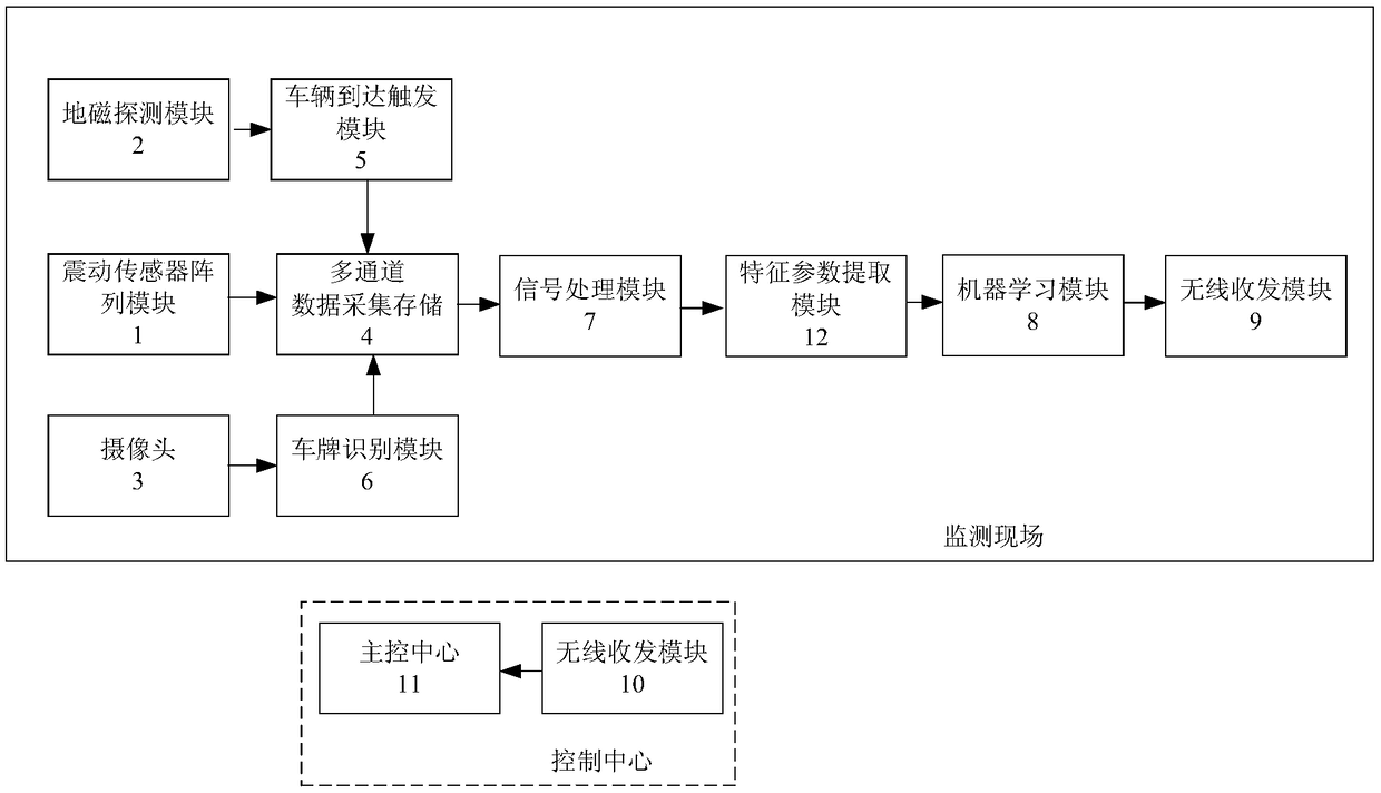
[0020] The present invention provides a vehicle dynamic overload monitoring system based on a distributed shock sensor array, which mainly consists of a shock sensor array module 1, a geomagnetic detection module 2, a camera 3, a multi-channel data acquisition system 4, a vehicle arrival trigger module 5, and a vehicle identification module 6. A signal processing module 7, a characteristic parameter extraction module 12, a machine learning module 8, a wireless transceiver module 9, a wireless transmission module 10 and a main control center 11;

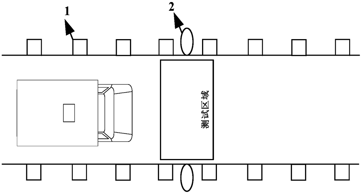
[0021] The vibration sensor array module 1 is composed of a plurality of vibration sensors symmetrically arranged on both sides of each lane, and the vibration sensor adopts a three-axis acceleration sensor (LIS344);

[0022] The vibration sens...


PUM


Abstract

The invention discloses a vehicle dynamic overload monitoring system based on a distributed vibration sensor array. The vehicle dynamic overload monitoring system is mainly composed of a vibration sensor array module, a geomagnetism detection module, a camera, a multi-channel data acquisition system, a vehicle arrival trigger module, a vehicle identification module, a signal processing module, a characteristic parameter extraction module and a machine learning module. The vibration sensor array is arranged on the bridge deck to perform overload measurement without damage to the pavement, and the construction period is short so as to greatly reduce the equipment installation and improve the work efficiency and the maintenance cost in the later period. Arrival of vehicles is judged by usinggeomagnetism information and overload measurement of the vehicle is performed in a noncontact manner by using the vibration sensor array so as to improve the driving speed of the vehicles in the overload monitoring process, effectively alleviate the traffic pressure of the urban roads and reduce the vehicle congestion rate during the rush hour. The relationship model between the vibration sensor array and the vehicle overload volume is established and applied to monitor vehicle overload so as to greatly improve the unattended efficiency of the highway overload monitoring system.

Description

technical field [0001] The invention belongs to the technical field of measurement, and in particular relates to a vehicle dynamic overload monitoring system based on a distributed vibration sensor array. Background technique [0002] As an important economic lifeline of a country, highways play an irreplaceable key role in communicating markets and material circulation. In recent years, my country's efforts to build road infrastructure, especially expressways, have increased year by year, and the amount of investment has continued to grow. However, due to the pursuit of the maximization of interests by some transporters, the phenomenon of overloading and exceeding the limit is common in my country's road transportation, which has caused great harm to traffic safety, transportation market and automobile production order. Therefore how to solve the increasingly urgent vehicle overloading, especially the minivan overloading problem that is not easy to monitor has become a top...

Claims


Application Information

Patent Timeline
Patent Type & Authority Applications(China)
IPC IPC(8): G01G19/03
CPCG01G19/03
Inventor 李剑闫欣韩焱潘晋孝王黎明苏新彦
Owner ZHONGBEI UNIV
Learn More