A metal hard-sealed spherical valve

A spherical valve, hard seal technology, applied in the direction of shaft seal, valve details, valve device, etc., can solve the problem of large installation space, etc., and achieve the effect of uniform wear, simple structure and small valve cavity volume

Active Publication Date: 2020-07-28
昆山三一环保科技有限公司
View PDF6 Cites 0 Cited by
  • Summary
  • Abstract
  • Description
  • Claims
  • Application Information

AI Technical Summary

Problems solved by technology

The sealing surface of the disc valve has the function of self-rotation and self-grinding, and has better wear resistance and sealing performance. However, since the valve disc needs to rotate eccentrically around the valve stem in the valve cavity, the valve body needs to be made relatively large and requires a larger The installation space has certain requirements for the orientation of the installation

Method used


Image

  • A metal hard-sealed spherical valve
  • A metal hard-sealed spherical valve
  • A metal hard-sealed spherical valve

Examples


Embodiment 1

[0032] figure 1 It is a structural schematic diagram of Embodiment 1 of a metal hard-sealed spherical valve of the present invention. In this embodiment, the metal-hard-sealed spherical valve mainly includes an inlet valve body 1, an outlet bonnet 2, a valve seat 3, and a spherical valve core 4. Spring seat 5, spring 6, valve core base 7, valve stem assembly 8, middle flange 9, packing assembly 10, packing gland 11, guide assembly 12.

[0033] In this embodiment, the inlet valve body 1 and the outlet valve cap 2 are connected by threaded fasteners and a valve chamber is formed inside the two, the valve core base 7 is arranged in the valve chamber, and a valve is provided on the side wall of the inlet valve body 1 Stem hole, the valve stem assembly 8 passes through the valve stem hole and is connected with the valve core base 7, wherein the end of the inlet valve body 1 away from the outlet bonnet 2 is provided with an inlet flow channel, the inlet flow channel and the valve ca...

Embodiment 2

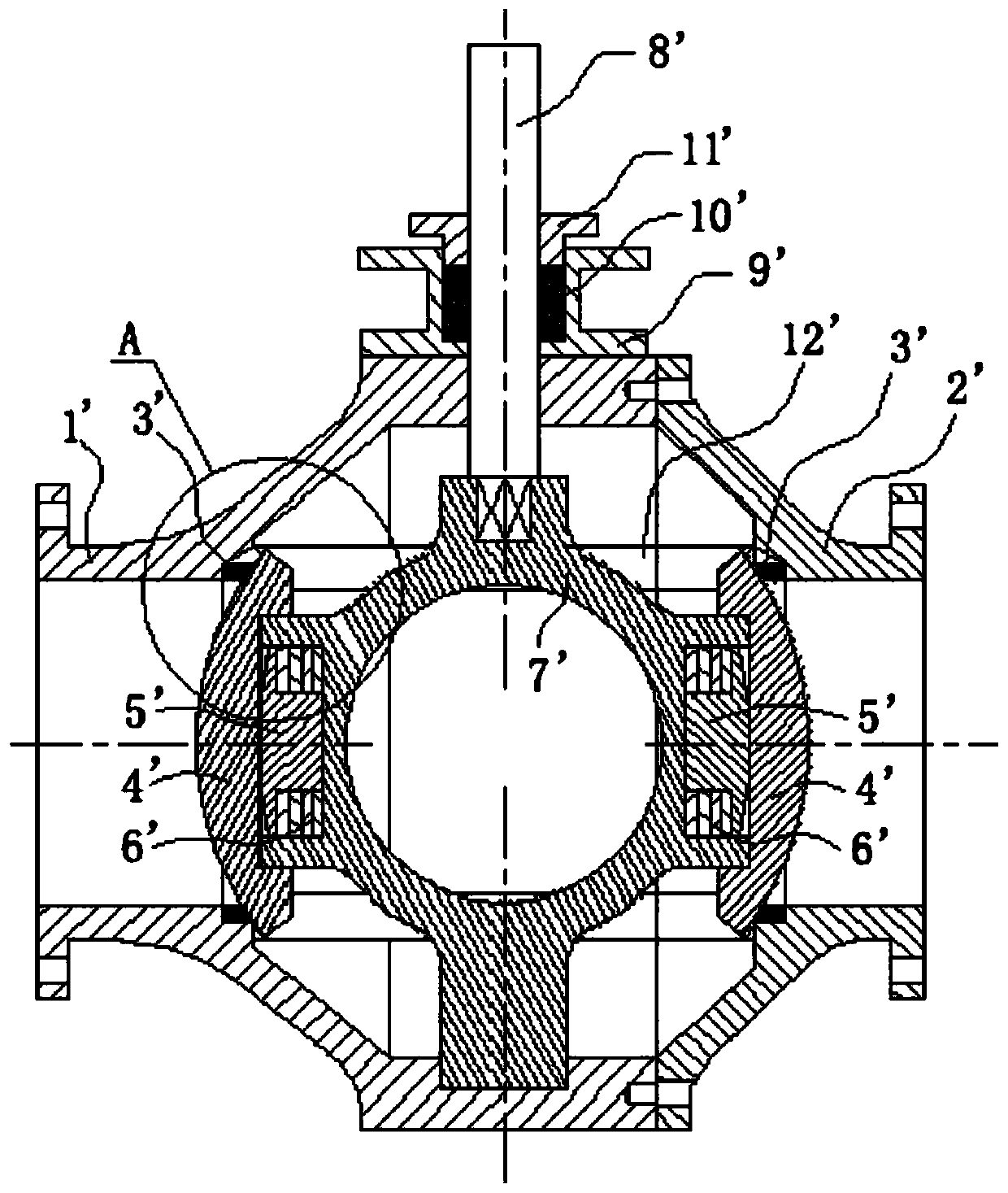
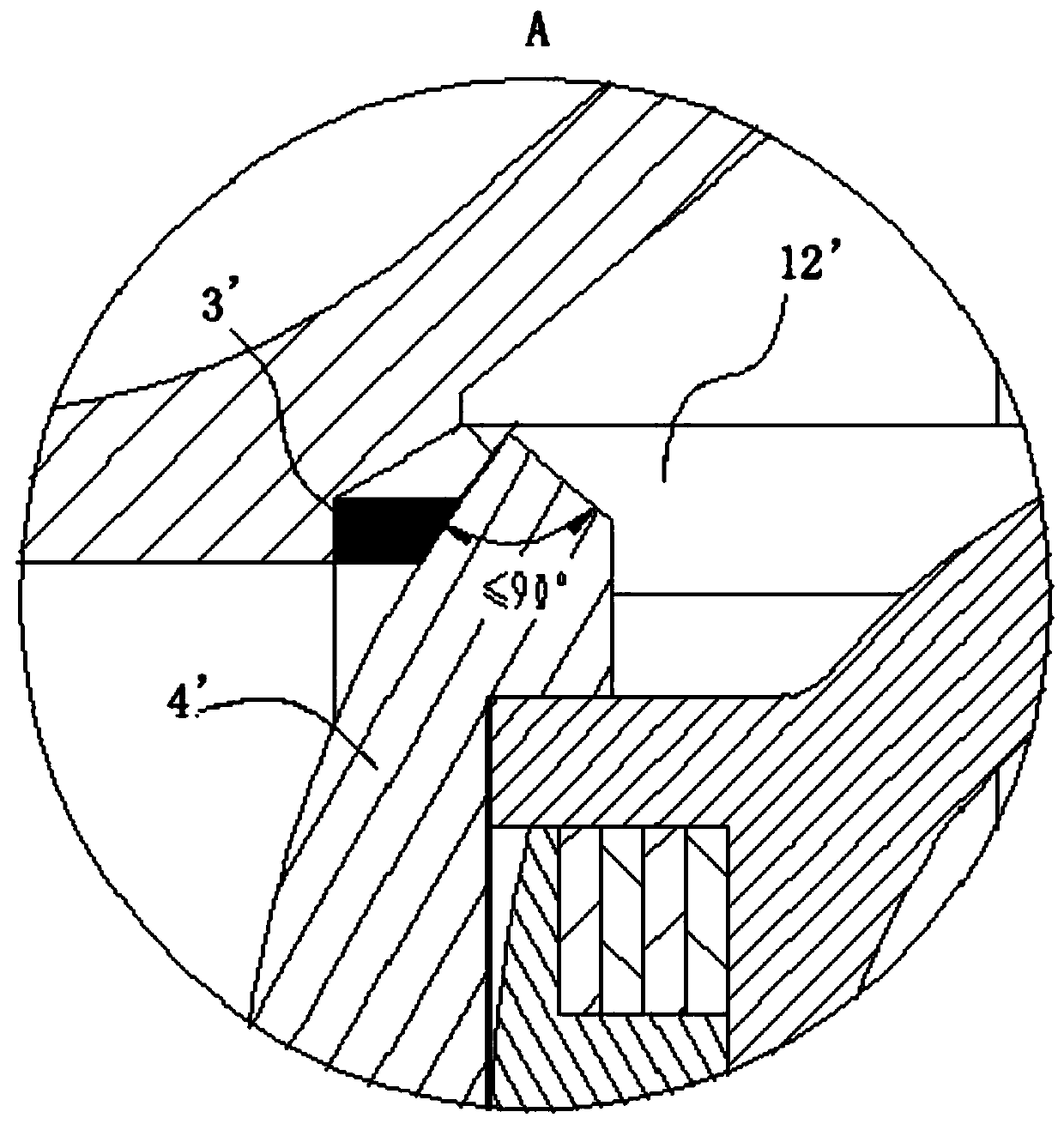
[0046] figure 2 It is a structural schematic diagram of Embodiment 2 of a metal hard-sealed spherical valve of the present invention; image 3 for figure 2 Partial enlarged view of the sharp knife structure of the spherical valve core at A. In this embodiment, the metal hard-sealed spherical valve mainly includes an inlet valve body 1', an outlet valve cap 2', a valve seat 3', and a spherical valve core 4 ', spring seat 5', spring 6', valve core base 7', valve stem assembly 8', middle flange 9', packing assembly 10', packing gland 11', guide assembly 12'.

[0047] In this embodiment, the inlet valve body 1' is connected to the outlet valve cap 2' and a valve cavity is formed inside the two, the valve core base 7' is arranged in the valve cavity, and a valve stem is provided on the side wall of the inlet valve body 1' hole, the valve stem assembly 8' passes through the valve stem hole and is connected with the valve core base 7', wherein the end of the inlet valve body 1' f...


PUM


Abstract

The invention discloses a metal hard sealing spherical valve, and belongs to the technical field of switching valves for conveying systems. The metal hard sealing spherical valve comprises a guiding track and a spherical valve element, wherein the guiding track is arranged in a valve cavity; the two ends of the guiding track communicate with an inlet flow channel and an outlet flow channel correspondingly; the guiding track comprises a valve seat and a guiding assembly; the valve seat is arranged on one side of the guiding assembly; the middle of a valve element base is arranged in the guidingassembly in the mode that the middle of the valve element base can rotate around the axis of a valve rod component; a valve element flow channel is formed in the middle of the valve element base; a guiding sleeve is arranged on one side of the middle of the valve element base; one side of the spherical valve element is rotationally arranged on the guiding sleeve in the axial direction of the guiding sleeve in a sleeving mode; the guiding sleeve is internally provided with an elastic support component; the edge of one side of the spherical valve element is attached to the guiding assembly; theedge of the other side of the spherical valve element is attached to the valve seat; and the edge of the spherical valve element is of a sharp-knife structure. The metal hard sealing spherical valveprovided by the invention is better in sealing effect, the size of the valve cavity is reduced, the weight is low, and the cost is low.

Description

technical field [0001] The invention relates to the technical field of on-off valves for conveying systems, in particular to a metal hard-sealed spherical valve. Background technique [0002] At present, in the conveying system of granular or powdery materials and slurry with high hardness, the sealing surface of traditional valves is easily invaded by the conveyed materials and causes wear. Disc valves and metal hard-sealed ball valves are mostly used in the market at present. The metal hard-sealed ball valve is small in size and mature in structure, but the contact point facing the sealing surface is fixed, and the wear resistance effect is slightly poor. The sealing surface of the disc valve has the function of self-rotation and self-grinding, and has better wear resistance and sealing performance. However, since the valve disc needs to rotate eccentrically around the valve stem in the valve cavity, the valve body needs to be made relatively large and requires a larger ...

Claims


Application Information

Patent Timeline
Patent Type & Authority Patents(China)
IPC IPC(8): F16K5/06F16K5/20F16K27/06F16K41/02
CPCF16K5/0605F16K5/0694F16K5/201F16K27/067
Inventor 石玉海程鹏立苏洲
Owner 昆山三一环保科技有限公司
Why Eureka
Try Eureka