
Manufacturing process for bearing rings

A manufacturing process and technology of bearing rings, applied in the direction of bearing components, shafts and bearings, engine components, etc., can solve the problems of poor anti-brittle performance of the structure, easy shaking, and reduced communication prohibition period

Inactive Publication Date: 2019-01-04
海安亚鼎机电制造有限公司
View PDF7 Cites 0 Cited by
  • Summary
  • Abstract
  • Description
  • Claims
  • Application Information

AI Technical Summary

Problems solved by technology

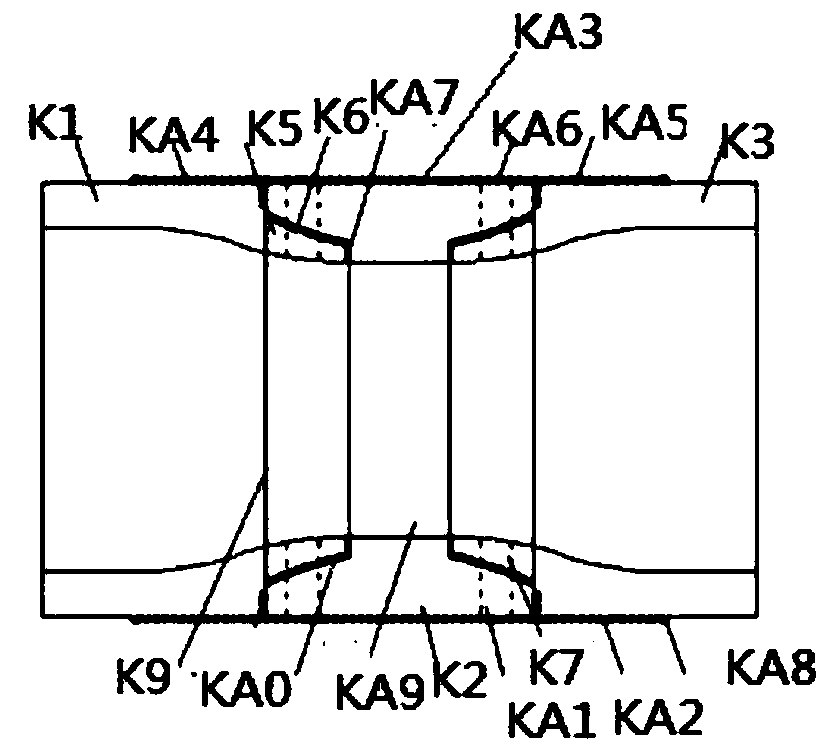
[0027] In order to solve the above problems, the present invention provides a manufacturing process for the bearing ring, which effectively avoids the unreliable and easy connection between the motor shaft and the coupling and the connection between the rotating rod and the coupling in the prior art. Shaking, too cumbersome plugging and poor anti-brittle performance of the connected structure, gaps between the motor shaft and the coupling and between the rotating rod and the coupling will also make the connection unreliable and easy to shake, communication prohibition period Decrease, reduce the period of time for blocking state, increase the running time of the controller, consume the controller resources and increase the power consumption of the controller, and the server duty cycle in the server chassis is too large to make the heat in the server chassis Too much accumulation will cause the server to ignite spontaneously, and the vertical span of the server case is too large, making it difficult for the maintainer to maintain the upper wall of the server case

Method used


Image

  • Manufacturing process for bearing rings
  • Manufacturing process for bearing rings
  • Manufacturing process for bearing rings

Examples


Embodiment Construction

[0084] The present invention will be further described below in conjunction with the accompanying drawings and embodiments.

[0085] Such as Figure 1-Figure 5 As shown, for the manufacturing process of the bearing ring, including the bearing ring manufacturing method described in the application number "201680051928.X", the application date is "2016.08.23" and the patent name is "bearing ring manufacturing method";

[0086] The bearing ring manufacturing method, the method comprising: a first step of setting a steel material heated to a temperature not lower than the A1 transformation point on a forming table and punching out a ring member from the steel material and thereafter forming and quenching the ring on the forming table The second step of the component;

[0087] The forming table includes a first mold and a second mold; the second mold is configured to be divided into an inner cylinder and an outer cylinder; in the second step, by placing a steel material between th...


PUM


Abstract

The invention discloses a manufacturing process for bearing rings. During assembling, a rib plate and an accommodating port are oppositely arranged; an opening and a projection are oppositely arranged; then, a rotating shaft of a motor and a sleeve at the head part of a rotating rod extend into embedding holes on two sides in a reinforced coupling for initial positioning; and the defects of looseconnection and easy shaking between the rotating shaft of the motor and the coupling and between the rotating rod and the coupling due to an insertion structure in the prior art, more complicated insertion, weak embrittlement resistance of the connected structure, reduction of the communication prohibiting period, reduction of the period for a blockage state, loss of controller resources and increment of the power consumption of the controller caused by increment of the operation time length of the controller, spontaneous combustion of a server due to excessive heat accumulation in a server chassis caused by longer working period of the server in the server chassis and difficult maintenance of the upper wall surface of the server chassis by maintainers due to larger vertical span of the server chassis are effectively prevented.

Description

technical field [0001] The invention relates to the technical field of manufacturing a bearing ring, in particular to a manufacturing process for a bearing ring. Background technique [0002] Press hardening is known as a technique for forming steel materials. Press hardening is a technique for press-forming a heated steel material and quenching the steel material by rapidly cooling the steel material in a die at the same time. [0003] A conventional method for manufacturing a rolling bearing ring of a thrust needle roller bearing includes many steps such as stamping, forming, heat treatment, quenching and tempering. Since the thickness of the rolling bearing ring of the thrust needle roller bearing is small, the setting steps before heat treatment are troublesome. Therefore, the costs for manufacturing rolling bearing rings are generally high due to the many steps in the manufacturing process. Therefore, it is necessary to be able to provide a cheaper rolling bearing ri...

Claims


Application Information

Patent Timeline
Patent Type & Authority Applications(China)
IPC IPC(8): B21K1/04B21H1/12F16C33/64
Inventor 王日华
Owner 海安亚鼎机电制造有限公司
Learn More