Optimal design method for reducing transient acoustic radiation of plate structure
A technology for optimizing design and sound radiation, applied in the direction of design optimization/simulation, calculation, instrument, etc., can solve unlikely problems, and achieve the effect of reducing transient sound radiation and realizing transient radiation sound pressure
- Summary
- Abstract
- Description
- Claims
- Application Information
AI Technical Summary
Problems solved by technology
Method used
Image

Examples
Embodiment 1
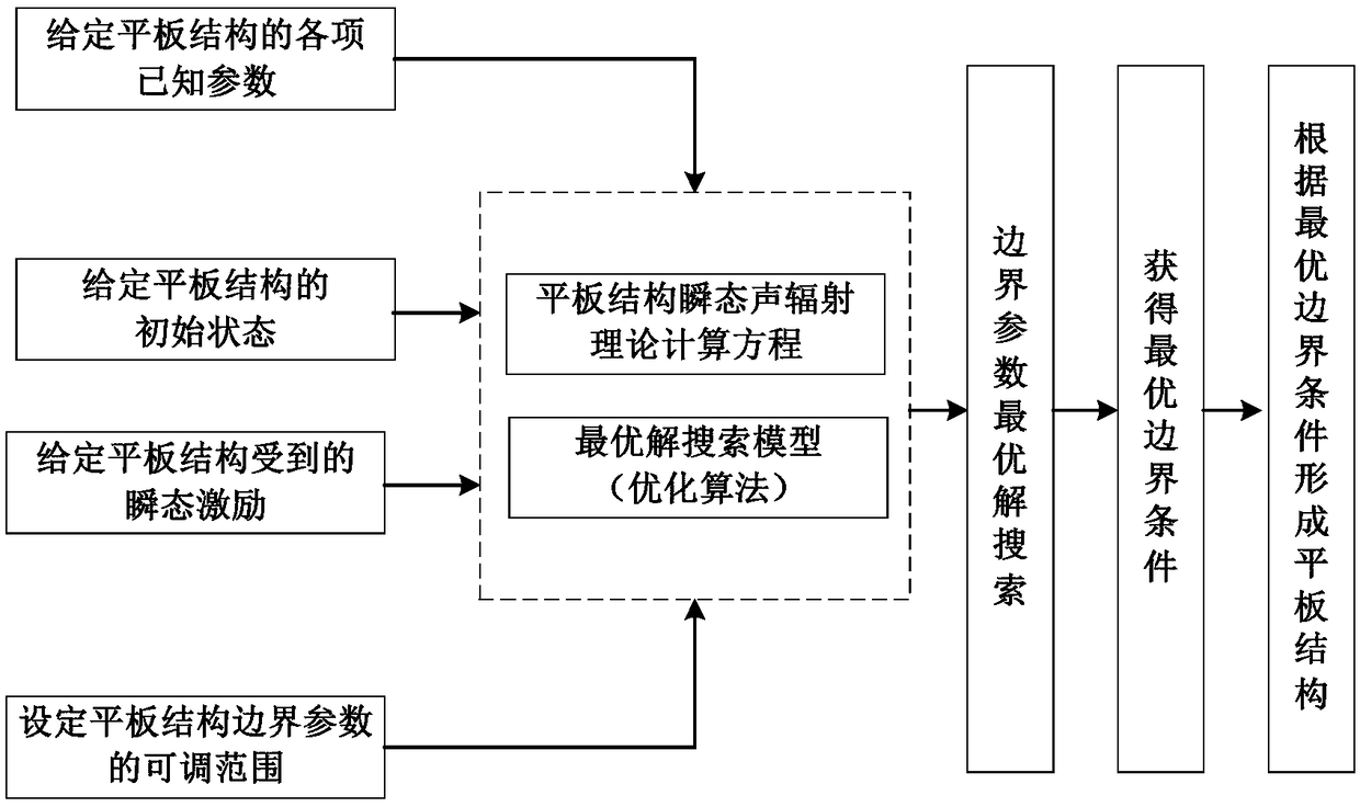
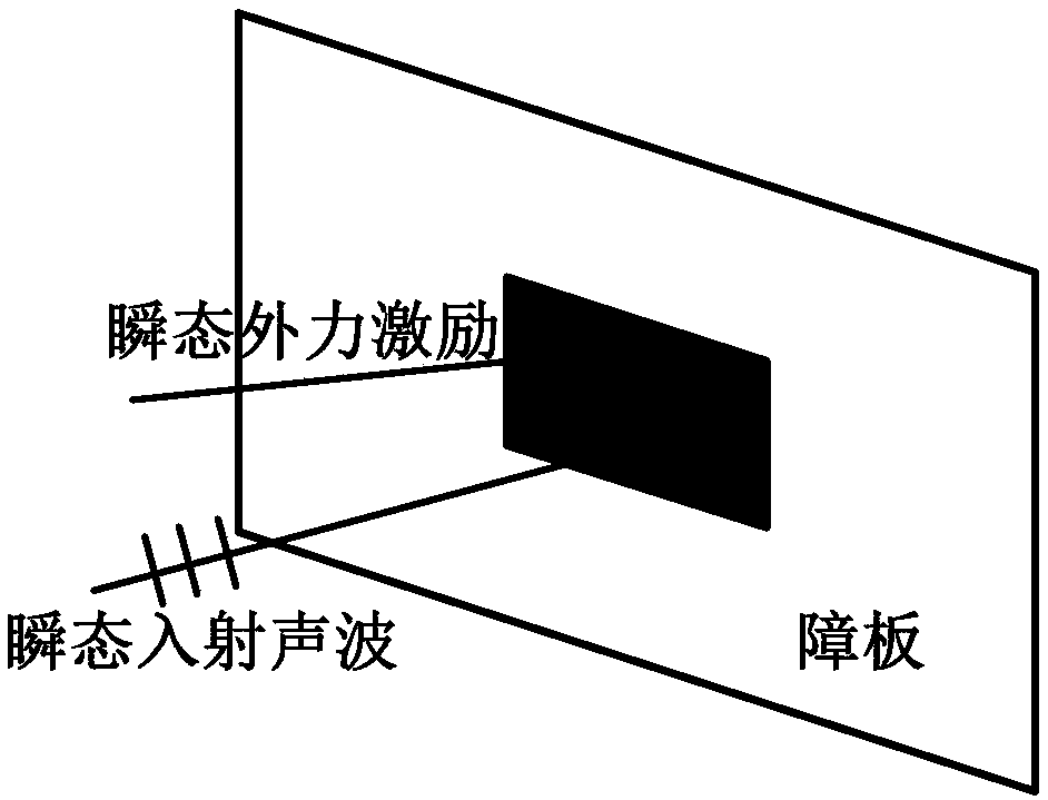
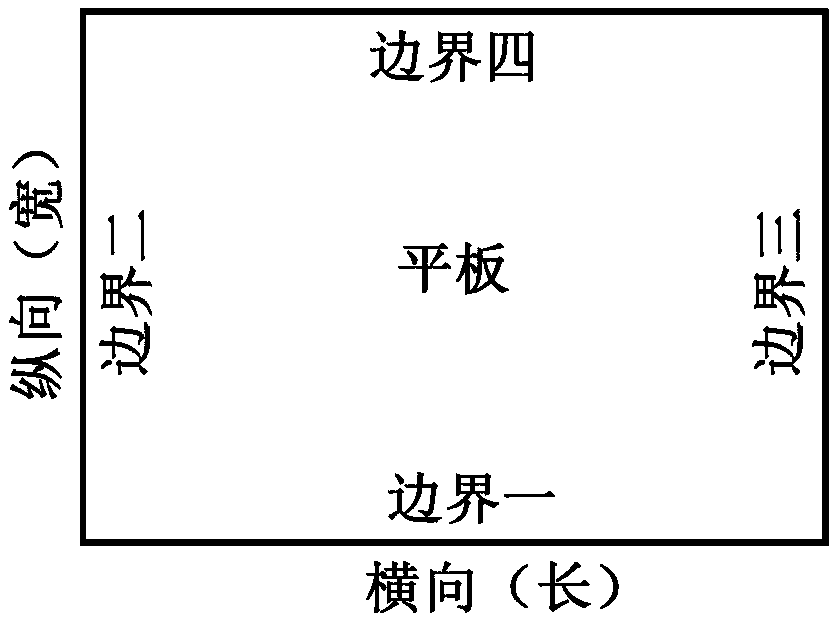
[0040] Embodiment one (structural schematic diagram sees figure 2 and image 3 ) The specific optimization steps are as follows:
[0041] Step 1. Based on the time-domain finite element-boundary element coupling method, establish a theoretical calculation equation for the transient sound radiation of a flat plate structure suitable for any boundary conditions:
[0042]
[0043] The derivation of the above formula is based on the time-domain finite element-boundary element coupling method, where SPL max is the maximum instantaneous radiated sound pressure level of the flat plate structure, p(ξ,t) is the instantaneous radiated sound pressure at ξ position at time t; S p is the plate area, ρ 0 is the air density, x is the coordinates of the plate nodes, c is the speed of sound, {R} is the transformation matrix, which is used to convert the node displacement of the plate structure into the transverse deflection, δ is the Dirac function, is the instantaneous nodal accelera...
Embodiment 2
[0087] Step 1. Based on the time-domain finite element-boundary element coupling method, establish a theoretical calculation equation for the transient sound radiation of a flat plate structure applicable to any boundary conditions;
[0088] Step 2. Set various known parameters of the plate structure, including plate material, plate damping factor, plate size and plate thickness, and set the specific position ξ for calculating the instantaneous radiated sound pressure. In this embodiment, ξ is set at a position 1m away from the flat structure on the center normal of the flat structure; the specific parameter values of the set flat structure are shown in the following table:
[0089]
[0090]
[0091] Step 3. Set the adjustable range of boundary parameters, as shown in the table below:
[0092]
[0093] Step 4. The initial state of the plate structure and the transient excitation received are given. The initial state given in this example is The center of the plat...
PUM
 Abstract
Description
Claims
Application Information
 - Generate Ideas
- Intellectual Property
- Life Sciences
- Materials
- Tech Scout
- Unparalleled Data Quality
- Higher Quality Content
- 60% Fewer Hallucinations
Browse by: Latest US Patents, China's latest patents, Technical Efficacy Thesaurus, Application Domain, Technology Topic, Popular Technical Reports.
© 2025 PatSnap. All rights reserved.Legal|Privacy policy|Modern Slavery Act Transparency Statement|Sitemap|About US| Contact US: help@patsnap.com