Manufacturing method of partition plate in multi-cylinder compressor
A technology of a compressor medium and a manufacturing method, applied in the field of compressors, can solve the problems of a lot of processing waste materials, poor processing conditions, low processing efficiency, etc., and achieve the effects of reducing processing costs, good dimensional accuracy, and ensuring strength and hardness
- Summary
- Abstract
- Description
- Claims
- Application Information
AI Technical Summary
Problems solved by technology
Method used
Image

Examples
Embodiment 1
[0029] In this embodiment, the two-cylinder compressor includes two sliding vanes, two pistons, two cylinders, one crankshaft, one main bearing, and one auxiliary bearing.
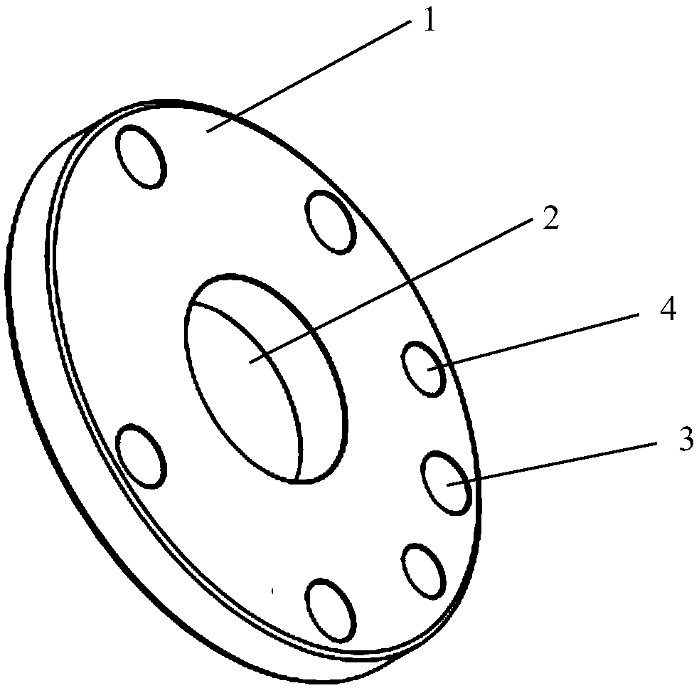
[0030] There is a partition 1 between the two cylinders, such as figure 1 As shown, the separator 1 is in the shape of a disk with a thickness of 9 mm, and a through hole 2 with a diameter of 30 mm is provided in the center of the disk for passing the crankshaft, and the diameter of the disk is 80 mm. In addition, installation through holes are provided on the partition 1, including five first through holes 3 with a diameter of 10 mm and two second through holes 4 with a diameter of 7 mm.
[0031] In this embodiment, a solid steel rod is used, and the steel rod has a cylindrical structure with a cross-sectional diameter of 80 mm. Through the cutting process, the cutting direction is perpendicular to the length direction of the steel bar, and a steel blank with a thickness of 3 mm is cut from the steel bar...
Embodiment 2
[0033] In this embodiment, the structure of the partition in the double-cylinder compressor is exactly the same as that in Embodiment 1.
[0034] In this embodiment, a hollow steel rod is used. The steel rod has a hollow cylindrical structure, and its cross section is a ring with an outer diameter of 80 mm and an inner diameter of 30 mm. Through the cutting process, the cutting direction is perpendicular to the length direction of the steel rod, and a steel blank with a thickness of 9 mm is cut from the steel rod. Then, a cutting piece with through holes 2, five first through holes 3, and two second through holes 4 is made on the steel blank by laser cutting, that is, as figure 1 separator shown.
Embodiment 3
[0036] In this embodiment, the two-cylinder compressor includes two sliding vanes, two pistons, two cylinders, one crankshaft, one main bearing, and one auxiliary bearing.
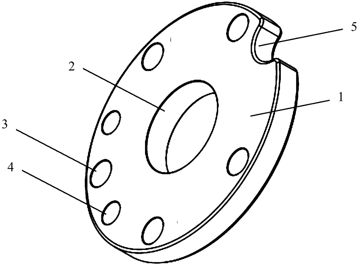
[0037] There is a partition 1 between the two cylinders, such as figure 2 As shown, the separator 1 is in the shape of a disk with a thickness of 15 mm, and a through hole 2 with a diameter of 30 mm is provided in the center of the disk for passing the crankshaft, and the diameter of the disk is 80 mm. The edge of the disc is in concave structure 5 . In addition, installation through holes are provided on the partition 1 , including five first through holes 3 with a diameter of 10 mm and two second through holes 4 with a diameter of 7 mm.
[0038] In this embodiment, a solid steel rod is used, and the steel rod has a cylindrical structure with a cross-sectional diameter of 80 mm. By cutting, the cutting direction is perpendicular to the length direction of the steel bar, and a steel blank with a thickne...
PUM
| Property | Measurement | Unit |
|---|---|---|
| Cross section diameter | aaaaa | aaaaa |
Abstract
Description
Claims
Application Information
 - Generate Ideas
- Intellectual Property
- Life Sciences
- Materials
- Tech Scout
- Unparalleled Data Quality
- Higher Quality Content
- 60% Fewer Hallucinations
Browse by: Latest US Patents, China's latest patents, Technical Efficacy Thesaurus, Application Domain, Technology Topic, Popular Technical Reports.
© 2025 PatSnap. All rights reserved.Legal|Privacy policy|Modern Slavery Act Transparency Statement|Sitemap|About US| Contact US: help@patsnap.com