
High reflector screening method applied to optical cavity structure

A technology of high reflection mirror and screening method, which is applied in color/spectral characteristic measurement, material analysis through optical means, measurement device, etc. It can solve the problems of cumbersome, aggravated detection difficulty, and unsatisfactory detection effect.

Inactive Publication Date: 2018-12-28
深圳市卡普瑞环境科技有限公司
View PDF8 Cites 2 Cited by
  • Summary
  • Abstract
  • Description
  • Claims
  • Application Information

AI Technical Summary

Problems solved by technology

In the prior art, before using a detection instrument to detect the concentration of atmospheric molecules, it is usually necessary to calibrate the sensitivity coefficient (sensitivity coefficient) of the detection instrument with a standard gas of known concentration, and to calibrate the detection with a standard gas of known concentration. The sensitivity factor of the instrument will add additional complexity and steps to the detection; in addition, the purchase and transportation of standard gases may be expensive, cumbersome, and sometimes difficult to obtain standard gases (such as N 2 o 5 and NO 3 ), thereby exacerbating the difficulty of detection; in addition, the existing detection instruments are not ideal for the detection of ultra-low concentrations of atmospheric molecules

Method used

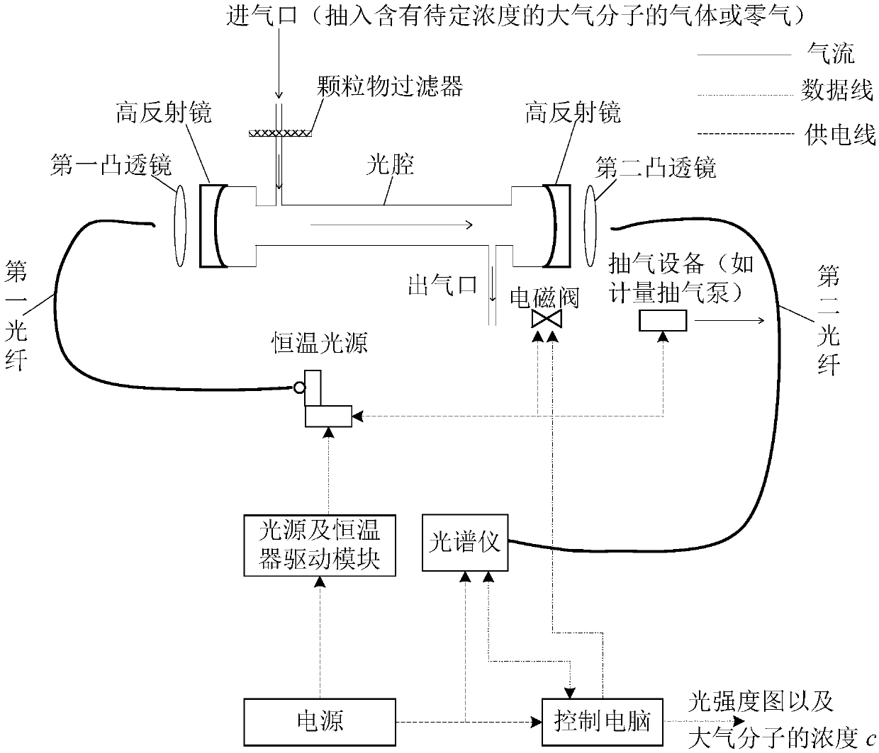

Image

  • High reflector screening method applied to optical cavity structure
  • High reflector screening method applied to optical cavity structure
  • High reflector screening method applied to optical cavity structure

Examples


Embodiment Construction

[0043] The following will clearly and completely describe the technical solutions in the embodiments of the application with reference to the drawings in the embodiments of the application. Apparently, the described embodiments are only some, not all, embodiments of the application. Based on the embodiments in this application, all other embodiments obtained by persons of ordinary skill in the art without making creative efforts belong to the scope of protection of this application.

[0044] It should be noted that the terms "comprising" and "having" and any variations thereof in the embodiments of the present application are intended to cover non-exclusive inclusion, for example, a process, method, system, product, or process that includes a series of steps or units. The apparatus is not necessarily limited to those steps or units explicitly listed, but may include other steps or units not explicitly listed or inherent to the process, method, product or apparatus.

[0045] An...


PUM


Abstract

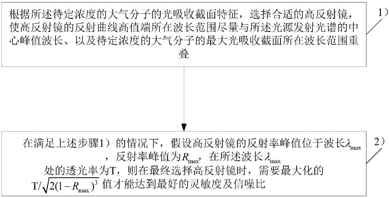
The invention provides a high reflector screening method applied to an optical cavity structure. The method comprises the following steps: 1) selecting a suitable high reflector according to light absorption cross section features of atmospheric molecules with concentration to be tested, and making a high value end of a reflection curve of the high reflector be overlapped with a wavelength range where a central peak wavelength of an emission spectrum of a light source and a maximum light absorption cross section of the atmospheric molecules with concentration to be tested as much as possible;and 2) in the case that the above step 1) is satisfied, assuming that the reflectivity peak of the high reflector is located at a wavelength lambda max, the reflectivity peak is Rmax, and the light transmittance at the wavelength lambda max is T, when the high reflector is selected at last, maximizing the value of (the formula is described in the specification) to achieve the best sensitivity andsignal to noise ratio. The optical cavity structure of the high reflector screened out by the method can not only effectively and conveniently detect the concentration of the atmospheric molecules, but also can effectively detect the concentration of atmospheric molecules with ultra-low concentration.

Description

technical field [0001] The present application relates to the technical field of environmental monitoring, in particular to a method for screening high reflection mirrors applied to optical cavity structures. Background technique [0002] With the continuous development of society and economy, air pollution has attracted more and more attention in most parts of the world, especially in developing countries. In order to detect the severity of air pollution, it is usually necessary to use detection instruments to analyze atmospheric molecules (such as gas molecules NO 2 , HCHO, CHOCHO, N 2 o 5 , NO 3 , HONO, aerosol, etc.) to detect the concentration. In the prior art, before using a detection instrument to detect the concentration of atmospheric molecules, it is usually necessary to calibrate the sensitivity coefficient (sensitivity coefficient) of the detection instrument with a standard gas of known concentration, and to calibrate the detection with a standard gas of kn...

Claims


Application Information

Patent Timeline
IPC IPC(8): G01N21/31G01N21/01
CPCG01N21/01G01N21/31
Inventor 欧阳彬王玉政
Owner 深圳市卡普瑞环境科技有限公司
Learn More