Artificial wave making device and method

A wave-making and artificial technology, applied in the field of artificial wave-making devices, can solve the problems of high energy, poor sustainability and long duration.

Active Publication Date: 2018-12-28
INST OF ELECTRICAL ENG CHINESE ACAD OF SCI
View PDF7 Cites 5 Cited by
  • Summary
  • Abstract
  • Description
  • Claims
  • Application Information

AI Technical Summary

Problems solved by technology

At present, the main methods that can produce waves with a certain professional level (sufficient wave height, sufficient duration after wave formation, and suitable wave shape) are vacuum method and wave-making plate traction method. One (reference patent: 201620641883.9) uses a vacuum pump to suck a certain amount of water to a certain height, then suddenly opens the valve and releases it into the pool, the impact forms waves, and the sucked water can also be replaced by a heavy object of a certain volume and weight. The method consumes a lot of energy, and the wave created will attenuate in the process of advancing after it is formed. The wave shape is a general swell, and the sustainability is poor; Pushing the pool water to form waves (refer to patents: PCT / ES2008 / 000089, PCT / US2013 / 059498, US8,366,347 B2, US 8,042,200 B2), the advantages are long duration and good wave shape (with obvious wave area, natural conditions The formation and breaking process of the lower wave is as follows: figure 1 ), the disadvantage is that the spatial geometry of the wave-making plate and the bottom of the pool is high, and it is necessary to use a supercomputer for numerical simulation calculation and optimization design. The design cycle of the whole set of equipment is long and the processing is difficult. For traction drive equipment, the power of the reference patent 2 is above 2.0MW. The volume and weight of the traction drive equipment are huge, and high-strength guide and support rails are required, which increases the construction cost and causes large additional friction and water viscosity. Resistance loss

Method used


Image

  • Artificial wave making device and method
  • Artificial wave making device and method
  • Artificial wave making device and method

Examples


Embodiment Construction

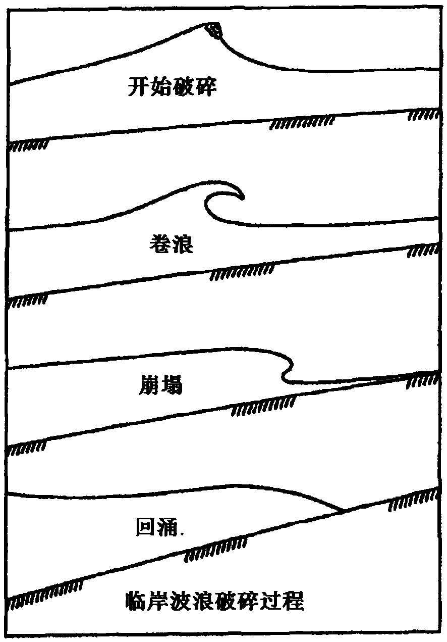
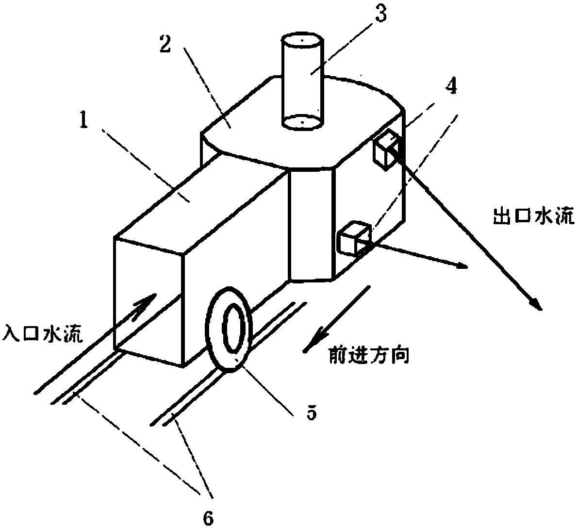
[0027] The present invention is a new type of artificial wave-making device which uses a water pump to drive the water flow and synthesizes various wave shapes vectorially in the pool through multiple jet outlets. The water pump installed on the wave-making device is sucked in from the front of the wave-making device through the water inlet. After the pool water is pressurized, jets are sprayed from one or more jets connected to the side of the wave-making device. According to the requirements of formula (3) and the specific project implementation conditions, multiple jets with different angles and speeds are The vector synthesis near the water surface of the wave pool, the speed and angle of the jet flow are determined by the formula (3), and waves of any wave height and wave shape can be formed, including curling waves, and there is no special requirement for the shape of the pool bottom. The present invention does not require external traction power, the wave-making device i...


PUM


Abstract

The invention relates to an artificial wave making device and method. According to the novel artificial wave making device, a water pump is used for driving water flow, and various wave types are formed in a pond by means of vector synthesis through a plurality of jet flow nozzles. The water pump installed on the wave making device sucks in pond water from the front portion of the wave making device through a water inlet, after pressurization, jet flow is sprayed from one or more jet flow nozzles connected with the side face of the wave making device at high speed, and the jet flow at different angles and speeds is subjected to vector synthesis close to the water surface of the pond so that waves, including plunging breakers, with any wave height and wave type can be formed. There are no special requirements for the shape of the bottom of the pond. External traction power is not needed, the wave making device has driving force, wheels installed on the lower portion of the wave making device move forward along a rail laid at the bottom of the pond, and continuous waves are formed in the pond.

Description

technical field [0001] The invention relates to an artificial wave-making device and method, and belongs to the category of a ship wave environment adaptability test platform, a wave power generation equipment test, and auxiliary facilities for mass sports and entertainment. Background technique [0002] Surfing originated from the Polynesians on the Pacific Islands. European nautical explorers discovered and recorded it in the 18th century. Its written records have been recorded for more than 200 years. Today, there are more than 35 million surfing enthusiasts around the world. This number is still increasing rapidly. In 2016, surfing officially became an Olympic event, and the World Surfing Association (WSL) also set up a Greater China region including mainland China, Hong Kong, Macao and Taiwan. But all over the world, the distribution of coasts suitable for surfing is very scarce, and it is seasonal and time-sensitive. to four hours for surfing. Due to the flatness of...

Claims


Application Information

Patent Timeline
IPC IPC(8): E04H4/00
CPCE04H4/0006
Inventor 王厚生李仲一
Owner INST OF ELECTRICAL ENG CHINESE ACAD OF SCI
Why Eureka
Try Eureka