
An additional track system with a wheel forward/reverse converter and a wheeled vehicle

A technology of converters and wheels, applied in tracked vehicles, motor vehicles, transportation and packaging, etc., can solve the problems of stress concentration, inconvenience, volume and mass increase, etc., to increase the maximum torque, reduce the volume of the device, and reduce the grounding ratio pressure effect

Pending Publication Date: 2018-12-28
苗壮
View PDF2 Cites 5 Cited by
  • Summary
  • Abstract
  • Description
  • Claims
  • Application Information

AI Technical Summary

Problems solved by technology

Existing technologies for converting wheeled vehicles such as pickup trucks, cars, and SUVs into crawler running states can be classified into two types: one is that the driving force acts on the inner surface of the track, represented by the triangular track of Mattracks in the United States. Remove the original wheels and replace them with triangular tracks; this type of additional track is bulky and inconvenient to install and remove
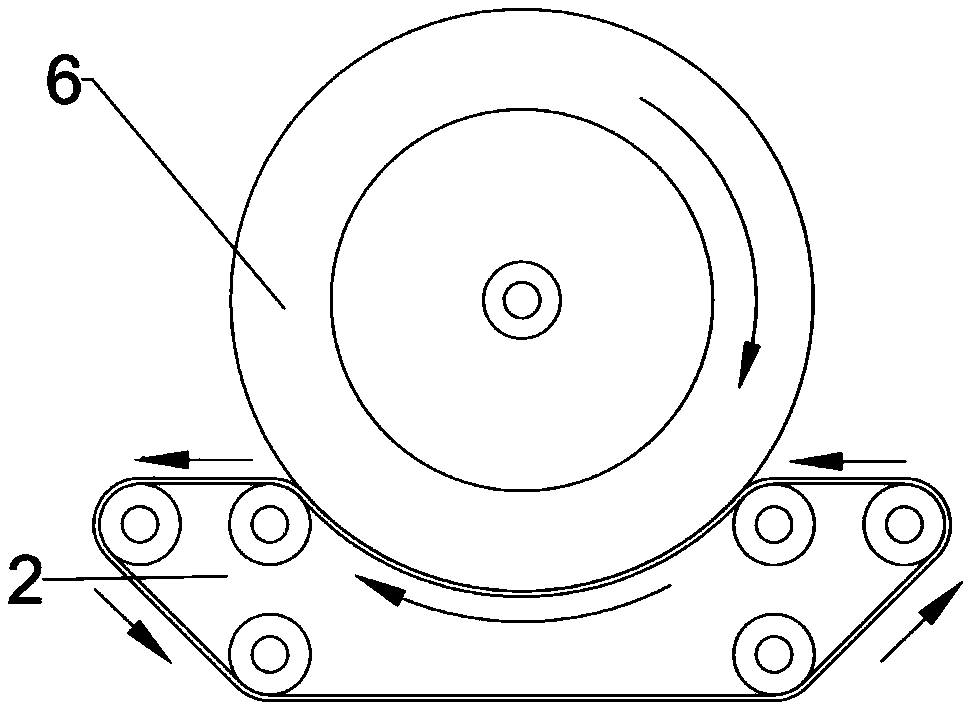
The other is that the driving force acts on the outer surface of the track, represented by the schemes recorded in US Patent US8776931 and Chinese Patent CN107650595; the original wheel does not need to be removed, but the rotation direction of the driving wheel and the driven wheel must be opposite after an external meshing transmission , so it is necessary to add an intermediate idler between the wheel and the track, and then reverse the direction of rotation through the drive of the intermediate idler to realize the same direction of track winding and wheel rotation; this solution does not need to remove the original wheel, but the wheel follows The contact area of ​​the intermediate idler is very small, and the wrap angle of the crawler on the idler is also less than 120 degrees. Only 1 to 3 teeth are involved in the drive. The stress concentration is serious, and it is easy to tear the tread and crawler.
To alleviate this problem, the existing technology chooses to design the diameter of the intermediate idler wheel as large as possible (usually greater than 25cm), resulting in an increase in the volume and quality of the device. Only large pickups can be carried with the car, and the convenience is not high.

Method used


Image

  • An additional track system with a wheel forward/reverse converter and a wheeled vehicle
  • An additional track system with a wheel forward/reverse converter and a wheeled vehicle
  • An additional track system with a wheel forward/reverse converter and a wheeled vehicle

Examples


Embodiment 1

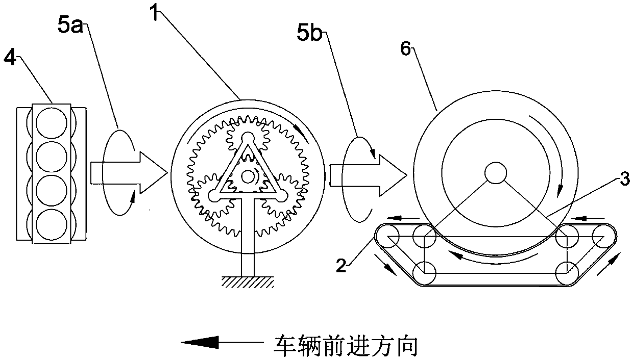
[0037] Embodiment 1: see Figure 4 , the wheel forward and reverse converter 1 is arranged between the output shaft of the prime mover 4 and the gearbox 13, the sun gear of the wheel forward and reverse converter is connected to the output shaft of the prime mover, the ring gear is connected to the input shaft of the gearbox, and the ring gear is fixed Attached to vehicle chassis.

[0038] see Figure 5 , the three circles in the figure are the pitch circles of the sun gear, planetary gear, and ring gear; a-the pitch circle diameter of the sun gear; b-the pitch circle diameter of the planetary gear; c-the pitch circle diameter of the ring gear. Obviously the moment M acting on the sun gear 1 =F 1 r 1 ;Moment M acting on the ring gear 3 =F 3 r 3 ;Moment M acting on planet carrier H H =F H r H .

[0039] Define the gear ratio of the ring gear and the sun gear as α, that is, α=Z / Z=r / r.

[0040] By gear geometry: r 3 = αr 1 、r H =(r 1 + r 3 ) / 2=r 1 (1+α) / 2.

[0...

Embodiment 2

[0052] Embodiment 2: The wheel forward and reverse converter is arranged after the gearbox and before the differential. The advantages and disadvantages are similar to those of Embodiment 1.

Embodiment 3

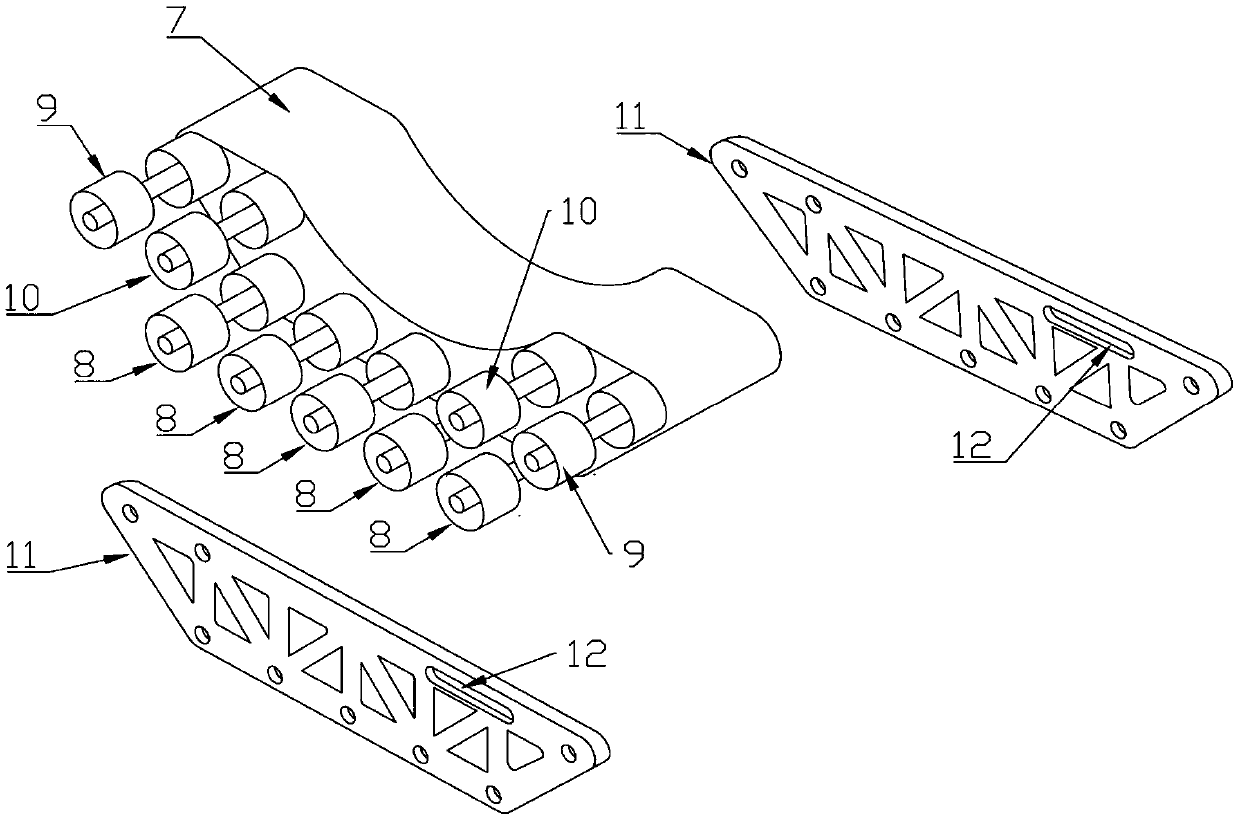
[0053] Embodiment 3: The wheel forward and reverse converter is embedded in the wheel hub of the vehicle drive wheel, see Figure 6 , Figure 7 . The wheel reversing device is connected with the crawler track running parts through the wheel-shoe connection assembly 3 with the planet carrier 19 on the upper part. The wheel-shoe connection assembly is a rod-plate truss structure with a triangular layout in general. Its top is processed with a ring, and a shaft hole for installing the planetary wheel shaft is opened on the ring, which acts as a planet carrier. The bottom of the connecting assembly is fixedly connected with the crawler frame. The sun gear 16 in the wheel forward and reverse converter is fixedly connected with the vehicle transmission half shaft 15, the ring gear 17 is fixedly connected with the rim, and the track frame is connected with the vehicle chassis through a metal chain. Tightly limit further tilting and play the role of anti-tilting mechanism. This em...


PUM


Abstract

An additional track system and wheeled vehicle with a wheel forward / reverse converter includes a wheel forward / reverse converter, a track traveling member and a wheel shoe connection assembly. The wheel forward / reverse converter includes a wheel forward / reverse converter, a track traveling member, and a wheel shoe connection assembly. When tracked driving is required, A track running device and awheel shoe connecting assembly are mounted on the lower part of the wheel, the track is pressed tightly by the vehicle gravity, the wheel is reversed by a wheel reversing mechanism, and after the tiredrives the outer surface of the track, the track section at the rear part of the track running part will be continuously retracted, and the track at the front part will be continuously released, andthe vehicle will travel forward under the action of winding force. The wheel forward-reverse converter is composed of a set of planetary gear train, including a sun gear, a planetary gear, a ring gearand a planet carrier. At that same time, the additional track system and wheeled vehicle with a wheel forward / reverse converter avoid the disadvantages that the additional track of the wheeled vehicle driven by the intermediate idle wheel is easy to produce the transmission stress concentration, the volume is large and the like, and has the advantages of convenient use, strong universality and low manufacture cost.

Description

technical field [0001] The invention belongs to the technical field of wheeled and crawler dual-purpose vehicles, and in particular relates to an additional crawler system with wheel forward and reverse converters and a wheeled vehicle. Background technique [0002] When driving on difficult road conditions such as sandy land, ice and snow, people hope to add a track system to the wheeled vehicle to improve its off-road capability. Existing technologies for converting wheeled vehicles such as pickup trucks, cars, and SUVs into crawler running states can be classified into two types: one is that the driving force acts on the inner surface of the track, represented by the triangular track of Mattracks in the United States. The original wheels are removed and replaced with triangular tracks; this type of additional track is bulky and inconvenient to install and remove. The other is that the driving force acts on the outer surface of the track, represented by the schemes record...

Claims


Application Information

Patent Timeline
IPC IPC(8): B62D55/04
CPCB62D55/04
Inventor 苗壮
Owner 苗壮
Learn More