A corn cutting device

A corn cutting technology, which is applied in metal processing and other directions, can solve problems such as uneven cutting, corn grain damage, and high labor intensity, so as to prevent deviation and deformation, improve service life, and solve the effects of being crushed

Active Publication Date: 2020-07-10
南通江海港建设工程有限公司
View PDF6 Cites 0 Cited by
  • Summary
  • Abstract
  • Description
  • Claims
  • Application Information

AI Technical Summary

Problems solved by technology

[0003] Due to the rich nutrition and sweet taste of corn, it is often used in cooking, especially in soup. In order to make the corn taste better and make the taste of corn blend into the soup, the corn is usually cut into small pieces before cooking. Soup; in general, at present, the operation of cutting corn into sections is that the chef cuts the corn into several small sections with a knife. Put the corn on the backing board, because it takes a lot of force to cut the corn into sections when cutting the corn, and the contact surface between the corn and the backing board is large, resulting in varying degrees of damage to the corn kernels on the side of the corn that is in contact with the backing board , crushing, affecting taste and appearance; in order to solve the problem of high labor intensity and low efficiency of manual operation with a knife, the patent application number 2014103018276 discloses a rotary knife type corn cutting machine, which adopts the method of vertically cutting the corn Straight into the feed pipe, the corn is naturally fed by gravity so that the lower end of the corn touches the pallet, and then the corn is cut into sections by the motor-driven rotating blade, which solves the problem of labor-intensive, low-efficiency, and uneven cutting of manual knife operations However, when the blade cuts the corn, the corn itself needs to bear the offset force of the feed tube on the cutter, so that the side of the corn opposite to the rotation direction of the blade is squeezed by the feed tube and the corn kernels are damaged. crushed situation

Method used


Image

  • A corn cutting device
  • A corn cutting device
  • A corn cutting device

Examples


Embodiment Construction

[0020] Now do further detailed explanation in conjunction with accompanying drawing.

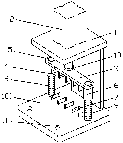
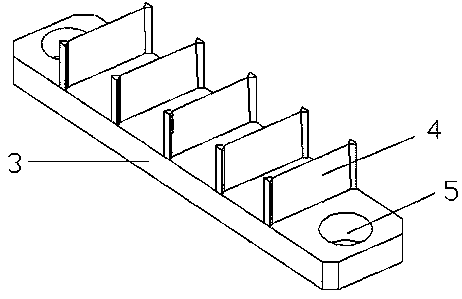
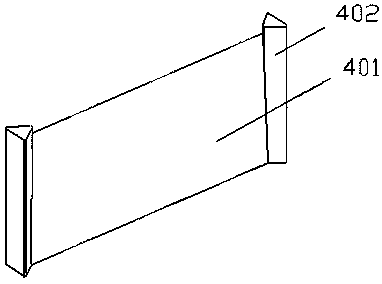
[0021] Such as Figure 1-4 Shown, a kind of corn sectioning device, it comprises formwork 1 and corn sectioning mould, and cylinder 2 is installed on the top of described formwork 1, and described corn sectioning mold is arranged on the base 101 of formwork 1 and is located on Below the cylinder shaft of the cylinder 2, the corn sectioning mold is provided with an upper template 3, and the bottom surface of the upper template 3 is provided with a row of cutters A4, and the two ends of the upper template 3 are provided with guide holes 5 and guide sleeves 6, and guide Cover 6 is installed on the guide hole 5, and the corn cutting mold also includes a row of cutters B7 and 2 guide pillars 8, the cutter B7 and guide pillars 8 are fixed on the base 101, and the guide pillars 8 are respectively equipped with springs 9, and the guide post 8 passes through the guide sleeve 6 and the guide hole 5 s...


PUM


Abstract

The invention discloses a corn cutting device which comprises a mould frame and a corn cutting mould. The top of the mould frame is provided with a gas cylinder. A corn cutting mould is arranged on abase and below a gas cylinder shaft of the gas cylinder. The corn cutting mould is provided with an upper mould board. the bottom surface of the upper mould board is provided with a row of cutter A. The two ends of the upper mould board are provided with a guide hole and a guide sleeve. The guide sleeve is installed on the guide hole. The corn cutting mould further comprises a row of cutter B andtwo guide columns. The cutter B and the guide columns are fixed on the base. The guide column is correspondingly provided with springs. The guide columns penetrate through the guide sleeve and the guide hole to make the upper mould board and the guide columns connected in a coordinated mode. The corn cutting device has a simple structure, even cutting sections, high efficiency of cutting corns andsolves the problem that corn kernels are crushed when cutting corns.

Description

technical field [0001] The invention relates to the field of corn processing, in particular to a corn cutting device. Background technique [0002] Corn is rich in nutrients: carbohydrates: 74.8 grams, protein: 29 grams, fat: 16.6 grams, dietary fiber 6.9 grams. It can be said that corn is well-deserved "the first golden staple food". According to nutrition experts, the "all-round nutrition" contained in corn is suitable for people of all ages. Its rich glutamic acid can promote brain development and is the best "food for children". The vitamin B group contained in it can regulate the nerves, and it is a "decompression food" suitable for white-collar workers; rich in linoleic acid and calcium, which can help regulate fat and lower blood pressure, and the high fiber content makes corn a very Good "intestinal scraping food" can prevent middle-aged obesity; in addition, glutathione rich in corn is the most effective anti-cancer ingredient, and its rich vitamin E can also help ...

Claims


Application Information

Patent Timeline
Patent Type & Authority Patents(China)
IPC IPC(8): B26D1/09B26D5/12
CPCB26D1/0006B26D1/09B26D5/12B26D2001/0033B26D2001/004
Inventor 劳加斌
Owner 南通江海港建设工程有限公司
Why Eureka
Try Eureka