Slurry overflow preventing variable cross-section cement-soil mixing pile head

A technology of cement-soil mixing pile and variable section, which is applied to sheet pile walls, soil protection, construction, etc., can solve the problems of large settlement deformation, smaller diameter of the pile body, and single shape of the pile body, so as to improve the quality of the pile. , The effect of reducing delamination and saving drilling time

Inactive Publication Date: 2018-12-25
GUANGDONG UNIV OF TECH
View PDF5 Cites 2 Cited by
  • Summary
  • Abstract
  • Description
  • Claims
  • Application Information

AI Technical Summary

Problems solved by technology

However, there are some defects in the current construction technology of cement-soil mixing piles. The pile quality is unstable, the pile body is delaminated, and the pile body is not mixed vertically, resulting in the pile body being in the shape of a thousand-layer cake, and the cement slurry is poured into the pile. When the foundation is in the ground, because the density is smaller than that of the soil, the cement slurry will go up, resulting in uneven distribution of cement slurry and uneven strength of the pile body.
The shape of the pile body is single, the strength of the pile body is low, and the diameter of the pile body will become smaller locally. These technical problems often lead to engineering quality problems such as large settlement deformation, cracking, slope instability, and sudden collapse in soft soil areas. The cost even affects the normal operation

Method used


Image

  • Slurry overflow preventing variable cross-section cement-soil mixing pile head
  • Slurry overflow preventing variable cross-section cement-soil mixing pile head
  • Slurry overflow preventing variable cross-section cement-soil mixing pile head

Examples


Embodiment 1

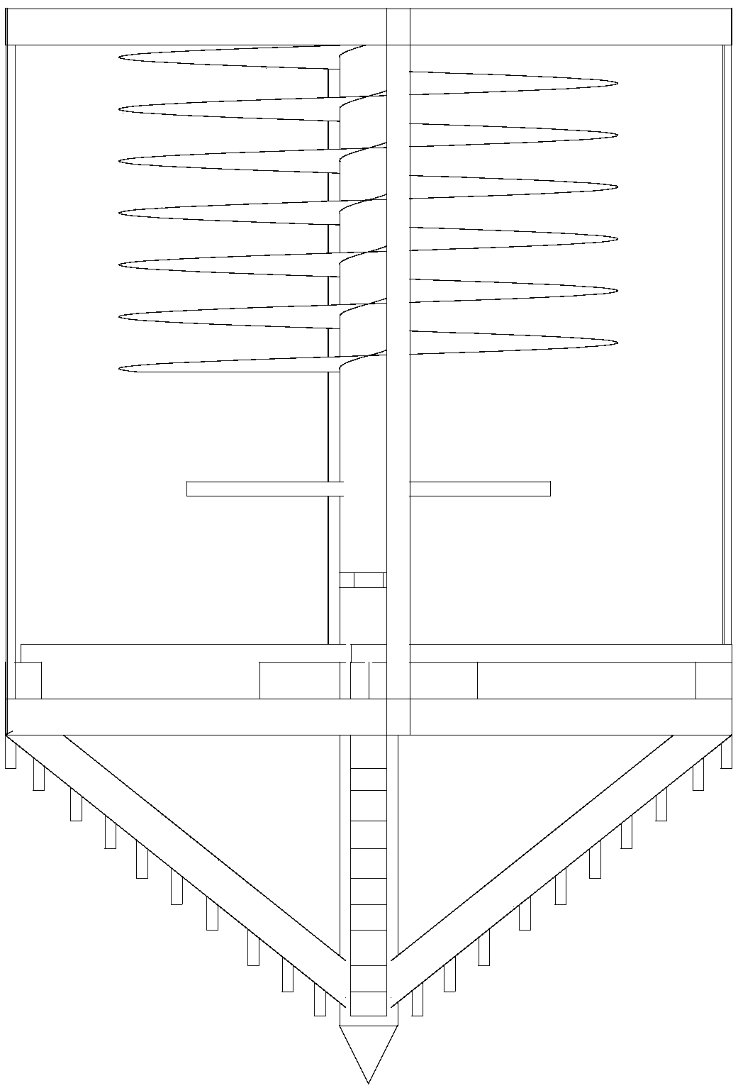
[0030] Such as Figure 1 to Figure 4 As shown, this embodiment discloses a cement-soil mixing pile head with a variable cross-section for anti-overflow, which mainly includes a pile head body 1, a rotating rod 2 arranged in the pile head body 1, and a cone for drilling A drill bit, an edge expansion part for enlarging the diameter of the pile, a stirring blade 5 for preventing slurry overflow, and a slurry inlet channel 6 for transporting cement slurry. The top of the pile head body 1 is connected to the power shaft of the construction equipment through transmission, and the pile head body 1 is driven to rotate. The conical drill bit is arranged at the bottom of the pile head body 1 and is fixedly connected with the pile head body 1 . The edge expansion part is arranged at the bottom of the pile head body 1, above the conical drill bit, and can extend outward or shrink inward. When extending outward and cutting the soil, the diameter of the pile can be enlarged. The stirring...


PUM


Abstract

The invention discloses a slurry overflow preventing variable cross-section cement-soil mixing pile head which comprises a rotating rod, a bottom soil cutting blade, an edge blade tool bit, horizontalmixing rods, a steel frame framework, a spiral blade, a hydraulic propelling device, a blade supporting rigid block and other components. The pile head is rotated clockwise under the effect of a power device to cut soil downwards, a bottom blade cuts soil to be in a loosened state, after the height reaches the designed elevation, cement slurry is grouted into soil through a grouting channel, at the moment, the rotating direction of the rotating rod is changed, the rotating rod is rotated anticlockwise, the spiral blade presses down soil in the middle of a pile body, therefore, vertical ingredients of soil are more uniform, and the slurry overflow phenomenon is effectively restrained. The horizontal soil cutting blade is expanded outwards under propelling of the hydraulic propelling device, the soil cutting area is increased, and the effect of changing the diameter of the pile body is achieved. By means of the mixing pile head, the pile forming quality of mixing piles can be improved,the pile body bearing capacity can be improved, and the working efficiency can be improved. The slurry overflow preventing variable cross-section cement-soil mixing pile head has the advantages of being simple in structure, convenient to operate and easy to implement.

Description

technical field [0001] The invention relates to the field of building construction equipment, in particular to a cement-soil mixing pile head with variable cross-section for anti-overflow. Background technique [0002] Soft soil foundation is widely distributed in economically developed areas such as the southeast coast of my country and inland river and lake basins. The soft soil is loose, high in compressibility, and low in shear strength; it has high sensitivity, structural properties, and obvious rheology. Therefore, when building buildings on soft soil foundations, special attention must be paid to the deformation and stability of soft soil. Soft soil foundation reinforcement is a major technical problem faced by civil engineering construction fields such as urban construction, rail transit, highways, railways, airports, and municipal engineering. [0003] At present, there are many treatment methods for soft ground, such as compaction, drainage consolidation, etc., an...

Claims


Application Information

Patent Timeline
Patent Type & Authority Applications(China)
IPC IPC(8): E02D5/46E02D3/12
CPCE02D3/126E02D5/46
Inventor 柒雯罗庆姿梁文清杜永生
Owner GUANGDONG UNIV OF TECH
Why Eureka
Try Eureka