Collecting method for carbon and sulfur drilling cutting samples and collector

A technology of sample collection and carbon-sulfur drilling, applied in the direction of sampling devices, etc., can solve the problems of loss of samples, large amount of drilling samples, increase of drilling time, etc., and achieve the effect of saving time, reducing intermediate links, and saving drilling time

Inactive Publication Date: 2013-01-16
ZHENSHI GROUP EASTERN SPECIAL STEEL
View PDF5 Cites 0 Cited by
  • Summary
  • Abstract
  • Description
  • Claims
  • Application Information

AI Technical Summary

Problems solved by technology

[0003] 1. White paper is made of wood pulp or straw pulp. The main components are C elements and S elements, and white paper is easy to break. When the sample is clamped and high-temperature sharp sample scraps fall on the paper, the paper fibers It is easy to pollute the sample, resulting in high C and S elements during analysis
[0004] 2. Put the white paper under the sample, so that the sample is in contact with the white paper, and the outer surface of the sample such as inclusions, iron oxide scale, and dust will fall on the white paper. When collecting the scrap sample, these impurities are collected together, causing errors in the analysis data
[0005] 3. When drilling samples, the surface scraps need to be discarded. If you use a brush to remove the scraps on the surface, it will take a long time and it is difficult to clean them. If you take off the white paper and pour it out, you need to re-clamp the sample , time-consuming, difficult to meet the requirements of rapid analysis
[0006] 4. Lay the white paper flat under the sample to drill the sample. Part of the sample debris splashes out of the white paper and the sample is lost. In order to achieve the sample size, a large amount of drilled sample is required, which increases the drilling time
[0007] 5. Every time a sample is drilled, the paper is easy to break, and the paper needs to be replaced for the next sample

Method used


Image

  • Collecting method for carbon and sulfur drilling cutting samples and collector

Examples


Embodiment Construction

[0020] The present invention will be further described in detail below in conjunction with the accompanying drawings and examples. The following examples are explanations of the present invention and the present invention is not limited to the following examples.

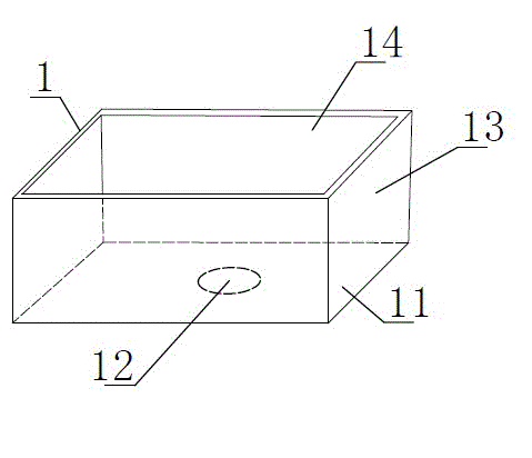
[0021] The carbon-sulfur drilling cuttings sample collection method of the present embodiment comprises the following steps, using a drill press to drill off the surface sample cuttings of the sample; a carbon-sulfur drilling cuttings sample collector is placed above the sample, and the collector is provided with a passage for the drill bit to pass through The drill bit drills into the sample through the through hole, and the drill cuttings of the sample are discharged upward through the chip removal groove of the drill bit and fall into the collector; after the collector finishes collecting the sample, it is directly taken to the analysis room together with the collector for analysis sample.

[0022] see figure 1 ...


PUM

PropertyMeasurementUnit
heightaaaaaaaaaa

Abstract

The invention discloses a collecting method for carbon and sulfur drilling cutting samples and a collector. The collecting method comprises the steps that surface sample cuttings of a sample are drilled off through a drilling machine; and a carbon and sulfur sample collector is placed above the sample, a through hole for a drill to penetrate through is opened in the collector, the drill penetrates through the through hole into the sample, and drilling cuttings of the sample are discharged upwards through a cutting discharge groove of the drill and drop in the collector. The collector comprises a box with an upper opening, and the through hole for the drill to penetrate through is opened at the bottom of the box. Compared with the prior art, the collecting method for carbon and sulfur drilling cutting samples and the collector have the advantages that the collector itself cannot contaminate cutting samples. The sample and a collecting surface of the collector are separated completely. The sample drilling time is saved as the sample cuttings are not lost by the collector. The sample and the collector are taken together to an analysis room to analyze the sample directly, so that an intermediate link of the sample packaging is reduced, and time is saved.

Description

technical field [0001] The invention relates to a method for collecting samples of carbon-sulfur drill cuttings and a collector. Background technique [0002] At present, carbon-sulfur drilling samples in the laboratory usually use clean white paper to pad under the sample. When drilling samples, the sample chips are collected on the white paper. This collection method has the following disadvantages: [0003] 1. White paper is made of wood pulp or straw pulp. The main components are C elements and S elements, and white paper is easy to break. When the sample is clamped and high-temperature sharp sample scraps fall on the paper, the paper fibers It is easy to contaminate the sample, resulting in high C and S elements during analysis. [0004] 2. Put the white paper under the sample, so that the sample is in contact with the white paper, and the outer surface of the sample such as inclusions, iron oxide scale, and dust will fall on the white paper. When collecting the scrap ...

Claims


Application Information

Patent Timeline
Patent Type & Authority Applications(China)
IPC IPC(8): G01N1/08
Inventor 刘勇锋
Owner ZHENSHI GROUP EASTERN SPECIAL STEEL
Why Eureka
Try Eureka