
Thin-walled casing vibration reduction tooling

A thin-walled and tooling technology, applied in the field of mechanical processing, can solve problems such as poor rigidity, poor processing surface precision, and easy tool vibration

Inactive Publication Date: 2018-12-25
HUNAN SOUTH GENERAL AVIATION ENGINE CO LTD
View PDF6 Cites 6 Cited by
  • Summary
  • Abstract
  • Description
  • Claims
  • Application Information

AI Technical Summary

Problems solved by technology

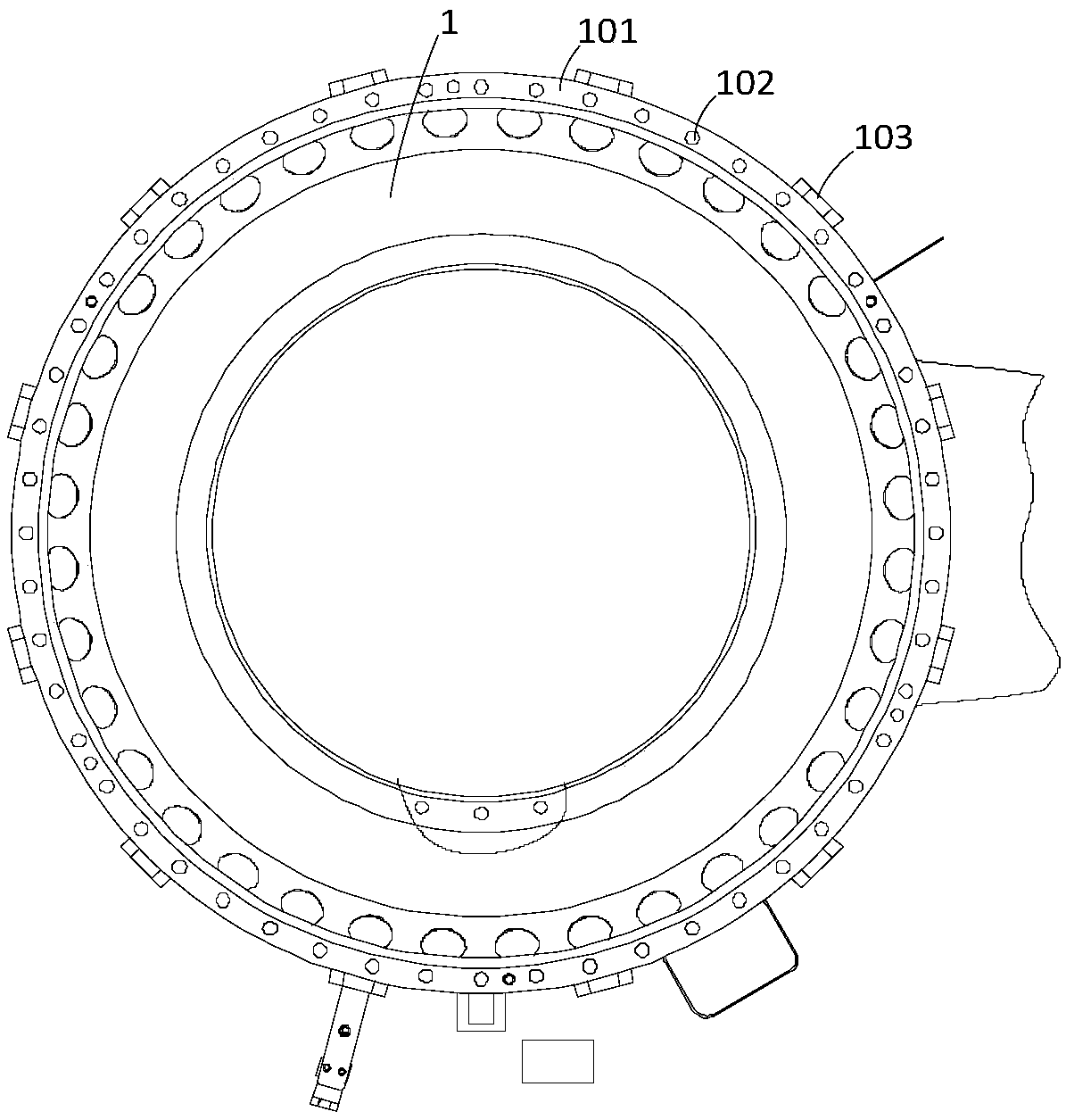
[0002] Due to the thin wall thickness, poor rigidity and poor cutting performance of thin-walled parts, it is easy to vibrate the tool during the next step of processing, resulting in poor precision of the processed surface. figure 1 As shown in the thin-walled casing 1, the processing content of the thin-walled casing 1 is 3 groups of 58 mounting holes 102 on the mounting side 101, and the wall thickness of the mounting side 101 is 2.05mm. The walls are tied with rubber belts along the circumferential direction to reduce vibration to a certain extent, but since the height of the thin-walled casing 1 is 400mm, the thickness of the casing wall is only 0.3-2mm, and there are multiple sets of casings in the middle of the casing wall. Welding the boss hole 103, resulting in serious insufficient structural rigidity of the thin-walled casing 1, extremely poor machinability, hole diameter precision cannot be guaranteed, pull hooks are prone to appear on the hole wall, and the surface quality cannot be guaranteed, and rubber is tied to the outer circular wall of the thin-walled casing 1 Belt, can not completely eliminate the impact of vibration on parts and tools

Method used


Image

  • Thin-walled casing vibration reduction tooling
  • Thin-walled casing vibration reduction tooling
  • Thin-walled casing vibration reduction tooling

Examples


Embodiment Construction

[0026] The object of the present invention is to provide a thin-walled casing vibration-damping tool, the structural design of the thin-walled casing vibration-damping tooling can improve the structural rigidity of the thin-walled casing, reduce the vibration during processing, and eliminate the impact of vibration on parts and tools. influence and improve its machinability.

[0027] The following will clearly and completely describe the technical solutions in the embodiments of the present invention with reference to the accompanying drawings in the embodiments of the present invention. Obviously, the described embodiments are only some, not all, embodiments of the present invention. Based on the embodiments of the present invention, all other embodiments obtained by persons of ordinary skill in the art without making creative efforts belong to the protection scope of the present invention.

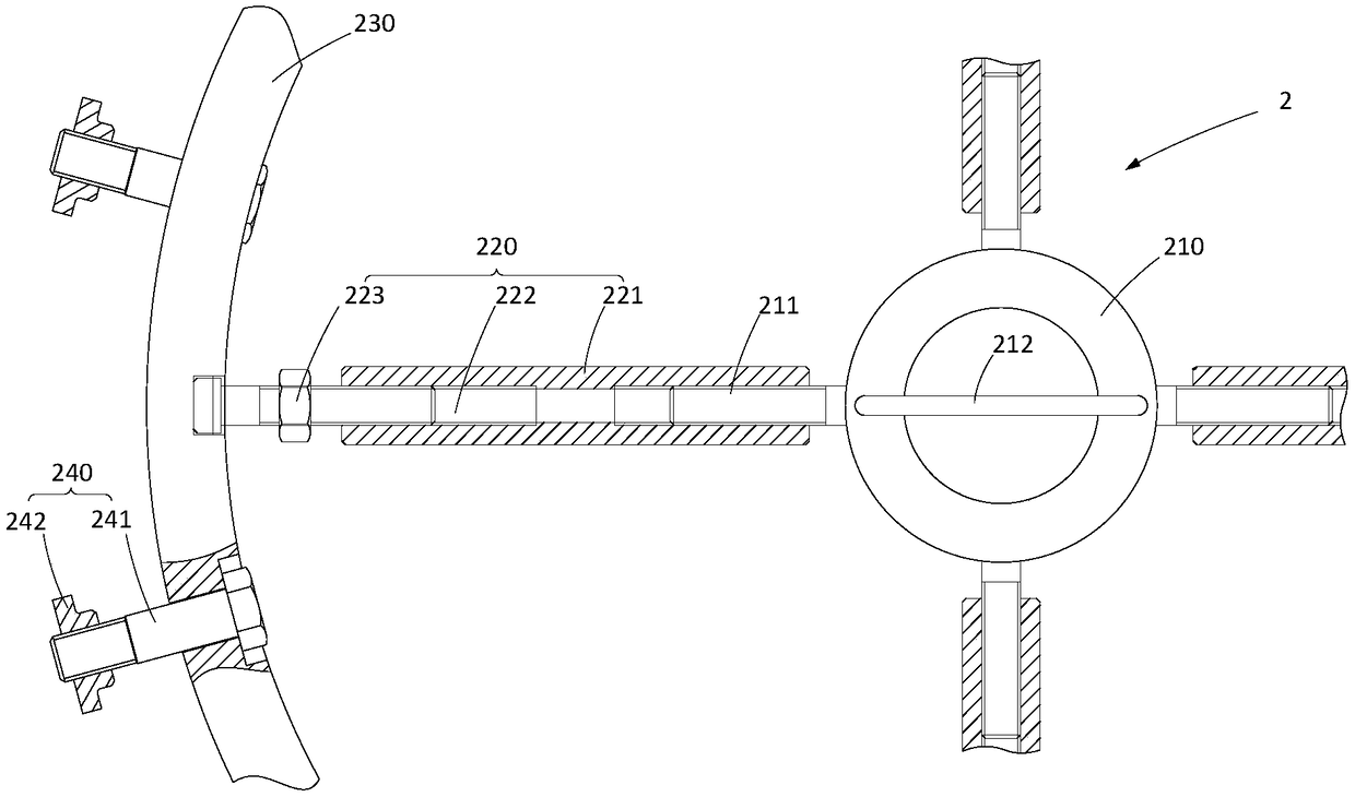
[0028] see figure 2 , figure 2 Schematic diagram of the structure of the thin-wa...


PUM


Abstract

The invention discloses thin-walled casing vibration reduction tooling. The thin-walled casing vibration reduction tooling comprises a bracket main body, support rods and cushion blocks, wherein at least two screw rods are radially and uniformly distributed on the bracket main body in the circumferential direction; the first ends of the support rods are connected with the screw rods; the outer wall surfaces of the cushion blocks are laminated with the inner wall of a casing; in a range from the inner wall, at the current place, of the casing to the inner wall, corresponding to a welding boss hole of the casing, of the casing, a ring-shaped gasket is formed by arranging a plurality of cushion blocks in a encircling manner; the cushion blocks are rotatably connected with the second ends of the support rods in a clamping manner. During the application, the cushion blocks are laminated on the inner wall of the casing, the support rods are connected with the screw rods on the bracket main body, and the support rods are rotated to ensure that the cushion blocks are supported on the inner wall of the casing, so that a firm and steady support structure is formed in the casing, the structural rigidity of the thin-walled casing is greatly strengthened, benefit is brought to eliminate the vibration during cutting, and influences, on parts and knifes, of the vibration are avoided, therebyimproving the cutting performance of the thin-walled casing, ensuring the precision of bore diameters, preventing pore walls from retraction and improving the machining surface quality.

Description

technical field [0001] The invention relates to the technical field of mechanical processing, in particular to a thin-wall casing vibration damping tool. Background technique [0002] Due to the thin wall thickness, poor rigidity and poor cutting performance of thin-walled parts, it is easy to vibrate the tool during the next step of processing, resulting in poor precision of the processed surface. figure 1 As shown in the thin-walled casing 1, the processing content of the thin-walled casing 1 is 3 groups of 58 mounting holes 102 on the mounting side 101, and the wall thickness of the mounting side 101 is 2.05mm. The walls are tied with rubber belts along the circumferential direction to reduce vibration to a certain extent, but since the height of the thin-walled casing 1 is 400mm, the thickness of the casing wall is only 0.3-2mm, and there are multiple sets of casings in the middle of the casing wall. Welding the boss hole 103, resulting in serious insufficient structura...

Claims


Application Information

Patent Timeline
IPC IPC(8): B23Q3/06
CPCB23Q3/065
Inventor 李彬邵聪邹吉亮黄靖王道徐宇超杨文彪曾继荣
Owner HUNAN SOUTH GENERAL AVIATION ENGINE CO LTD
Learn More