
Locomotive-buffer-bar surface repairing and remanufacturing method

A surface repair and buffer rod technology, which is applied in the direction of manufacturing tools, welding equipment, metal processing equipment, etc., can solve the problems of the working surface of the buffer rod, insufficient basic research, and large buffer distance, etc., to achieve fine grain size and metallurgical bonding Good, wear-resistant effect

Active Publication Date: 2018-12-25
SOUTHWEST JIAOTONG UNIV
View PDF6 Cites 6 Cited by
  • Summary
  • Abstract
  • Description
  • Claims
  • Application Information

AI Technical Summary

Problems solved by technology

But on the whole, the repair and remanufacturing of locomotive parts and other fields in my country is still in the state of exploration. At the same time, the domestic repair and remanufacturing process is relatively simple, the basic research is insufficient, there are few fields involved, the product is single, and the market recognition is low.
[0004] The buffer rod is one of the important components of the locomotive and vehicle connection buffer system. During long-term use, problems such as reduced buffering effect, larger buffer distance, and increased noise are prone to occur. The main reason is that the working surface of the buffer rod , aging and cracks
It is scrapped every year due to wear, deformation, scratches, corrosion, etc., resulting in a waste of social resources

Method used


Image

  • Locomotive-buffer-bar surface repairing and remanufacturing method
  • Locomotive-buffer-bar surface repairing and remanufacturing method
  • Locomotive-buffer-bar surface repairing and remanufacturing method

Examples


Embodiment

[0042] A method for repairing and remanufacturing the surface of a locomotive bumper bar, the steps are as follows:

[0043] S1. Detect and screen the damaged buffer rods after disassembly, remove the buffer rods with cracks and unqualified coaxiality through X-ray inspection and coaxiality detection, and screen out the repairable buffer rods to be repaired;

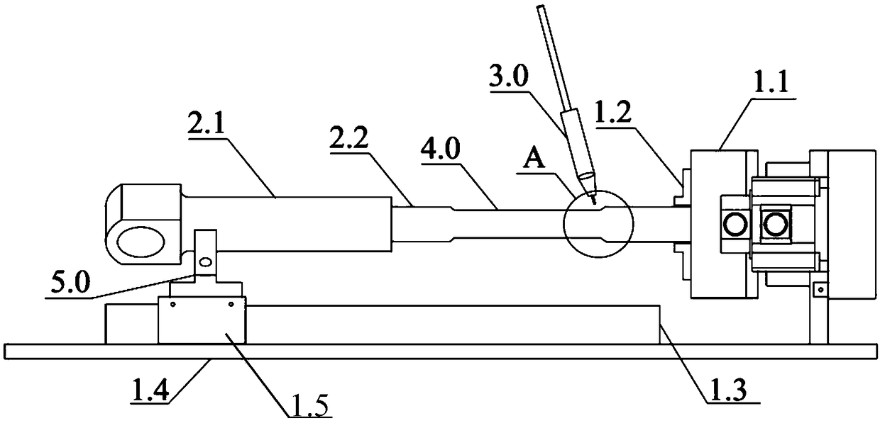
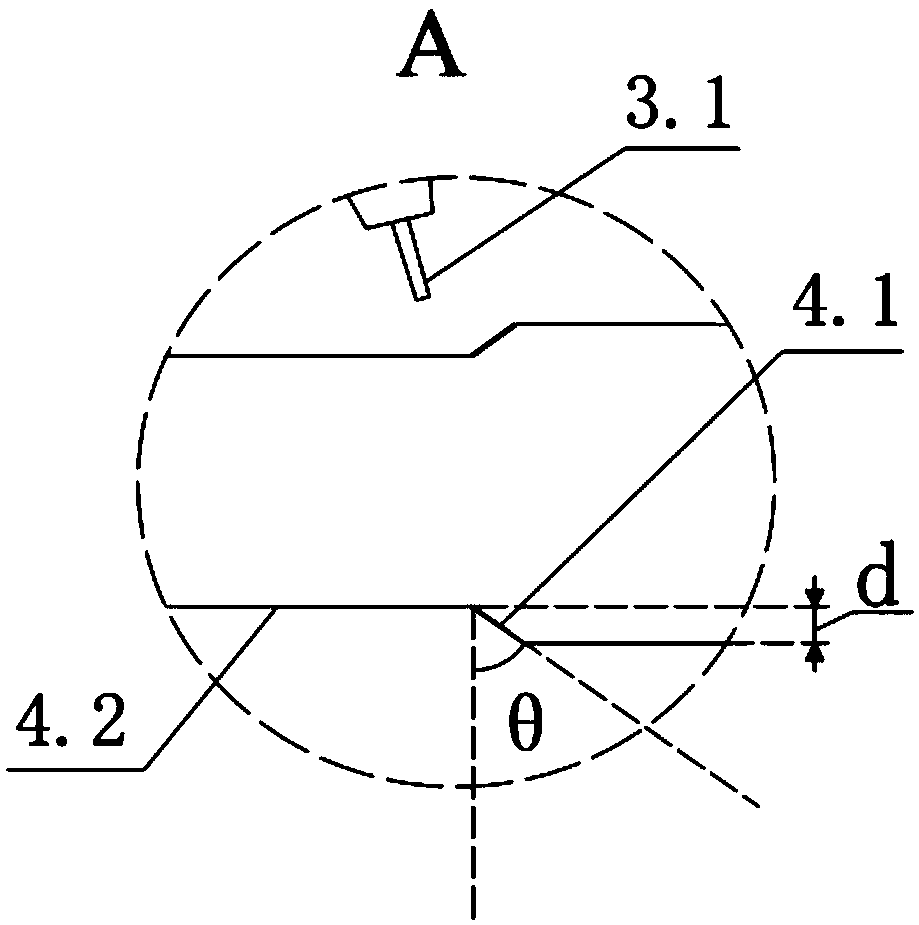
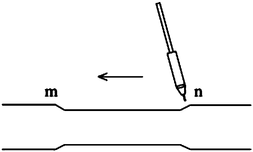
[0044] S2. Check the wear amount of the buffer rod to be repaired, respectively on the shaft sections of different radii of the buffer rod (the buffer rod includes a thick end and a thin end, the thick end is a large-radius shaft segment, and the thin end is a small-radius shaft segment. The thick end and thin end of the buffer respectively determine the area to be repaired and process the groove to be repaired, figure 1 Among them, the thick end of the buffer rod to be repaired does not need to be repaired, only the thin end wear needs to be repaired, and only the groove to be repaired is made on the thin end), the area...

Embodiment 1

[0060] S1. Detect and screen the damaged buffer rods after disassembly, remove the buffer rods with cracks and unqualified coaxiality through X-ray inspection and coaxiality detection, and screen out the repairable buffer rods to be repaired;

[0061] S2. Check the wear amount of the buffer rod to be repaired, and determine the area to be repaired according to the size of the wear amount in the shaft sections of different radii of the buffer rod, and process the groove to be repaired in the area to be repaired; in this example, the thickness of the buffer rod to be repaired is The end diameter is Φ75mm, the maximum wear depth is 3mm, and the wear length is about 20cm; the thin end diameter is Φ48mm, the maximum wear depth is 3mm, and the wear length is about 12cm;

[0062] On the butt end of the buffer rod to be repaired, the area to be repaired is determined according to the maximum wear depth and wear length of the butt end, and the groove to be repaired is processed in the a...

Embodiment 2

[0072] S1. Detect and screen the damaged buffer rods after disassembly, remove the buffer rods with cracks and unqualified coaxiality through X-ray inspection and coaxiality detection, and screen out the repairable buffer rods to be repaired;

[0073] S2. Check the wear amount of the buffer rod to be repaired, and determine the area to be repaired according to the size of the wear amount in the shaft sections of different radii of the buffer rod, and process the groove to be repaired in the area to be repaired; in this example, the thickness of the buffer rod to be repaired is The end diameter is Φ75mm, the maximum wear depth is 4mm, and the wear length is about 18cm; the thin end diameter is Φ48mm, the maximum wear depth is 4mm, and the wear length is about 14cm;

[0074] On the butt end of the buffer rod to be repaired, the area to be repaired is determined according to the maximum wear depth and wear length of the butt end, and the groove to be repaired is processed in the a...


PUM

PropertyMeasurementUnit
Diameteraaaaaaaaaa
Lengthaaaaaaaaaa
Lengthaaaaaaaaaa

Abstract

The invention discloses a locomotive-buffer-bar surface repairing and remanufacturing method. The locomotive-buffer-bar surface repairing and remanufacturing method includes the following steps that S1, repairable to-be-repaired buffer bars are screened out; S2, the abrasion loss of the to-be-repaired buffer bars is checked, to-be-repaired areas are determined on different-radius shaft segments ofthe buffer bars according to the size of the abrasion loss respectively, and to-be-repaired grooves are processed in the to-be-repaired areas; S3, the to-be-repaired buffer bars are sequentially subjected to sand blasting, cleaned and preheated; S4, one ends of the to-be-repaired buffer bars are fixed on a displacement device, and the to-be-repaired grooves are subjected to continuous annular welding through a CMT automatic welding system to complete repairing of the to-be-repaired buffer bars; S5, the repaired buffer bars obtained in the step S4 are welded to be subjected to slow cooling treatment; S6, the repaired areas of the repaired buffer bars are machined according to the size of an original-buffer-bar drawing, and then whole sand blasting is carried out. The locomotive-buffer-barsurface repairing and remanufacturing method is low in cost, high in efficiency and high in repairing quality, and the buffer bars after being repaired and remanufactured with the method can reach thequality standard of a new buffer bar.

Description

technical field [0001] The invention relates to a method for repairing and remanufacturing the surface of a buffer rod of a locomotive, and belongs to the technical field of surface repair and remanufacturing. Background technique [0002] With the rapid development of my country's economy in recent years, the transportation industry is in the stage of explosive growth. With the development of the transportation industry, the amount of scrap is also increasing, causing problems such as environmental pollution and waste of resources. Restoration and remanufacturing projects can alleviate the pressure on resources, have a prominent role in environmental protection, increase employment rates, contain high economic added value, and have good development prospects. [0003] The repair and remanufacturing of locomotive parts has become a development trend for effective utilization of resources and reduction of enterprise costs. But on the whole, the repair and remanufacturing of...

Claims


Application Information

Patent Timeline
IPC IPC(8): B23P6/00B23K31/02
Inventor 陈辉马彦龙庞西南胡登文梁盈
Owner SOUTHWEST JIAOTONG UNIV
Learn More