
Shift range control device

A control device and gear technology, applied in the direction of electronic reversing motor control, control system, stop device, etc., can solve problems such as fluctuations

Active Publication Date: 2018-12-21
DENSO CORP
View PDF11 Cites 3 Cited by
  • Summary
  • Abstract
  • Description
  • Claims
  • Application Information

AI Technical Summary

Problems solved by technology

In addition, motors using permanent magnets such as DC brushless motors have better responsiveness than SR motors, but on the other hand, if the feedback gain is increased to improve responsiveness, when the motor is stopped, there will be a problem due to cogging. Influenced by torque, etc., there is a hidden danger of hunting

Method used


Image

  • Shift range control device
  • Shift range control device
  • Shift range control device

Examples


no. 1 Embodiment approach

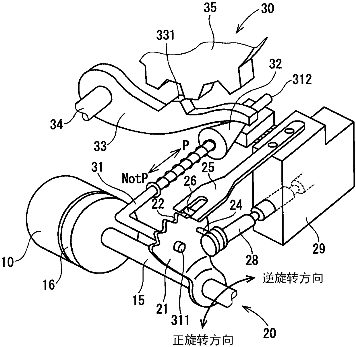
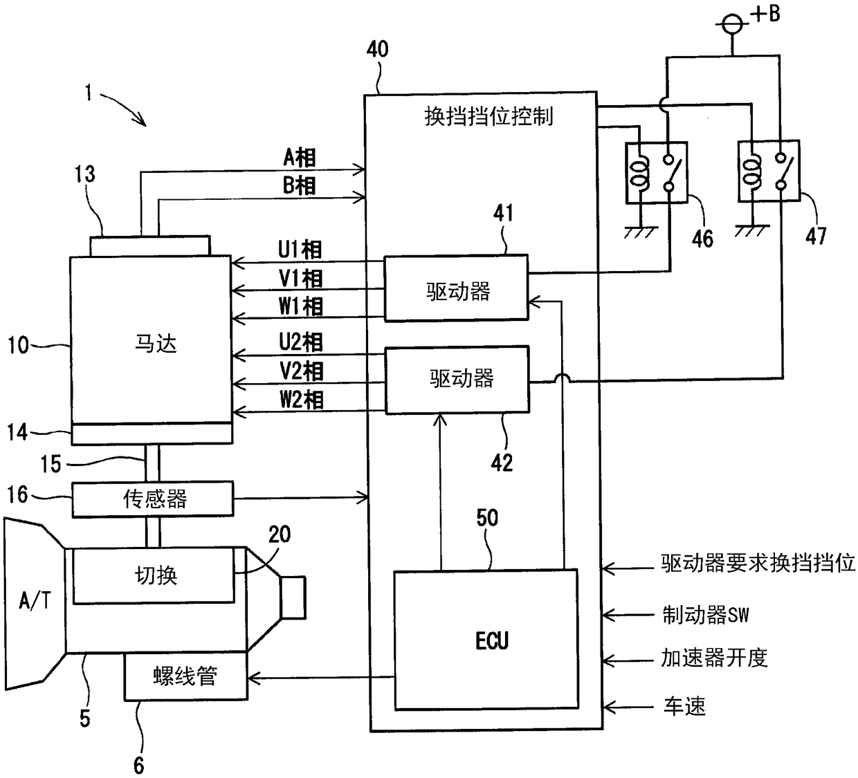
[0026] exist Figure 1 to Figure 6 The shift position control device according to the first embodiment of the present disclosure is shown.

[0027] like figure 1 and figure 2 As shown, the shift-by-wire system 1 includes a motor 10 , a shift position switching mechanism 20 , a parking lock mechanism 30 , a shift position control device 40 , and the like.

[0028] The motor 10 is powered by a battery 45 (refer to image 3 ) is rotated by being supplied with electric power, and functions as a driving source of the shift position switching mechanism 20 . As the motor 10 , a motor capable of changing the magnitude of the current through feedback control and changing the command for each phase can be used. The motor 10 of this embodiment is a permanent magnet type DC brushless motor. like image 3 As shown, the motor 10 has two sets of winding wires 11 , 12 . The first winding wire group 11 has a U1 coil 111 , a V1 coil 112 , and a W1 coil 113 . The second winding wire gro...

no. 2 Embodiment approach

[0091] exist Figure 7 , Figure 8A as well as Figure 8B The second embodiment of the present disclosure is shown in . In this embodiment, since the switching control process is different from the above-described embodiment, the description will focus on this point.

[0092] based on Figure 7 The shown flowchart describes the switching control process of this embodiment.

[0093] The processing of S201~S204 and Figure 5 The processing of S101 to S104 is the same.

[0094] In S205, the switching control unit 65 determines whether or not the angular deviation e is larger than the first angle determination threshold e_th1. The first angle determination threshold e_th1 is set to correspond to a value (for example, 1° in terms of mechanical angle) that does not cause overshoot when the motor speed Msp is large, even when the motor 10 is stopped from its high-speed rotation state. count value of . The first angle determination threshold e_th1 is set to a value larger than...


PUM


Abstract

This shift range control device switches shift range by controlling the drive of a motor (10). The shift range control device comprises a feedback control unit (52) that performs position feedback control on the basis of a target angle determined according to the requested shift range and the actual angle of the motor; a fixed phase ON / OFF control unit (61) that performs fixed phase ON / OFF controlthat provides power to a fixed phase selected according to an actual angle; and a switching control unit (65) that switches between motor control states. The switching control unit switches the control state to position feedback control when the requested shift range is switched. If the difference between the target angle and the actual angle drops to or falls below an angle determination threshold, the switching control unit switches the control state from position feedback control to fixed phase ON / OFF control.

Description

[0001] Cross-references to related applications [0002] This application is based on Japanese Patent Application No. 2016-81919 filed on April 15, 2016, and Japanese Patent Application No. 2016-176275 filed on September 9, 2016, and the contents thereof are incorporated herein by reference. technical field [0003] The present disclosure relates to a gear shift control device. Background technique [0004] Conventionally, there is known a shift position switching device that switches a shift position by controlling a motor in response to a shift position switching request from a driver. For example, in Patent Document 1, a switched reluctance motor is used as a drive source of a shift position switching mechanism. Hereinafter, the switched reluctance motor is referred to as "SR motor". [0005] The inventors of the present disclosure found the following problems. An SR motor that does not use permanent magnets has a simple structure. In addition, motors using permanent ...

Claims


Application Information

Patent Timeline
Patent Type & Authority Applications(China)
IPC IPC(8): H02P6/24F16H59/08F16H61/02F16H61/32F16H63/04H02P27/06
CPCF16H59/08F16H61/02F16H61/32F16H63/04H02P27/06H02P6/24F16H63/3425F16H2061/2823F16H2061/326H02P6/153F16H61/28
Inventor 神尾茂
Owner DENSO CORP
Learn More