
A thermodynamic deicing device of a transformer device

A technology of power transformation equipment and thermal power, applied in the direction of switchgear, electrical components, etc., can solve the problems of affecting large-area power supply, limited deicing effect, damage to power transformation equipment and other equipment, and achieve the effect of auxiliary cleaning

Active Publication Date: 2018-12-21
WENZHOU ELECTRIC POWER DESIGN +1
View PDF7 Cites 3 Cited by
  • Summary
  • Abstract
  • Description
  • Claims
  • Application Information

AI Technical Summary

Problems solved by technology

However, in some cities with low temperature all year round, rain, snow and freezing weather often cause great damage to substation equipment, and will bring hidden dangers of frost cracking to coupling capacitors, CTs, busbar pillar porcelain bottles and other equipment in substations. If the equipment is greatly affected, it will affect the power supply of a large area, which will have a great impact on people's lives and even cause serious losses
[0003] Among them, the transformer on the road will also be affected by icing and low temperature, which will cause the internal substation to fail to work normally, and the ceramic shell of the internal components will be affected by freezing cracks, etc.
[0004] And due to the lack of effective deicing means and methods, in order to avoid accidents after substation equipment is covered with ice, manual cleaning and beating deicing methods are mainly used. This method has limited deicing effect, and the labor intensity of the staff is high. Easy to cause damage to equipment such as substation equipment

Method used


Image

  • A thermodynamic deicing device of a transformer device
  • A thermodynamic deicing device of a transformer device
  • A thermodynamic deicing device of a transformer device

Examples


Embodiment Construction

[0019] The present invention will be described in further detail below in conjunction with the embodiments given in the accompanying drawings.

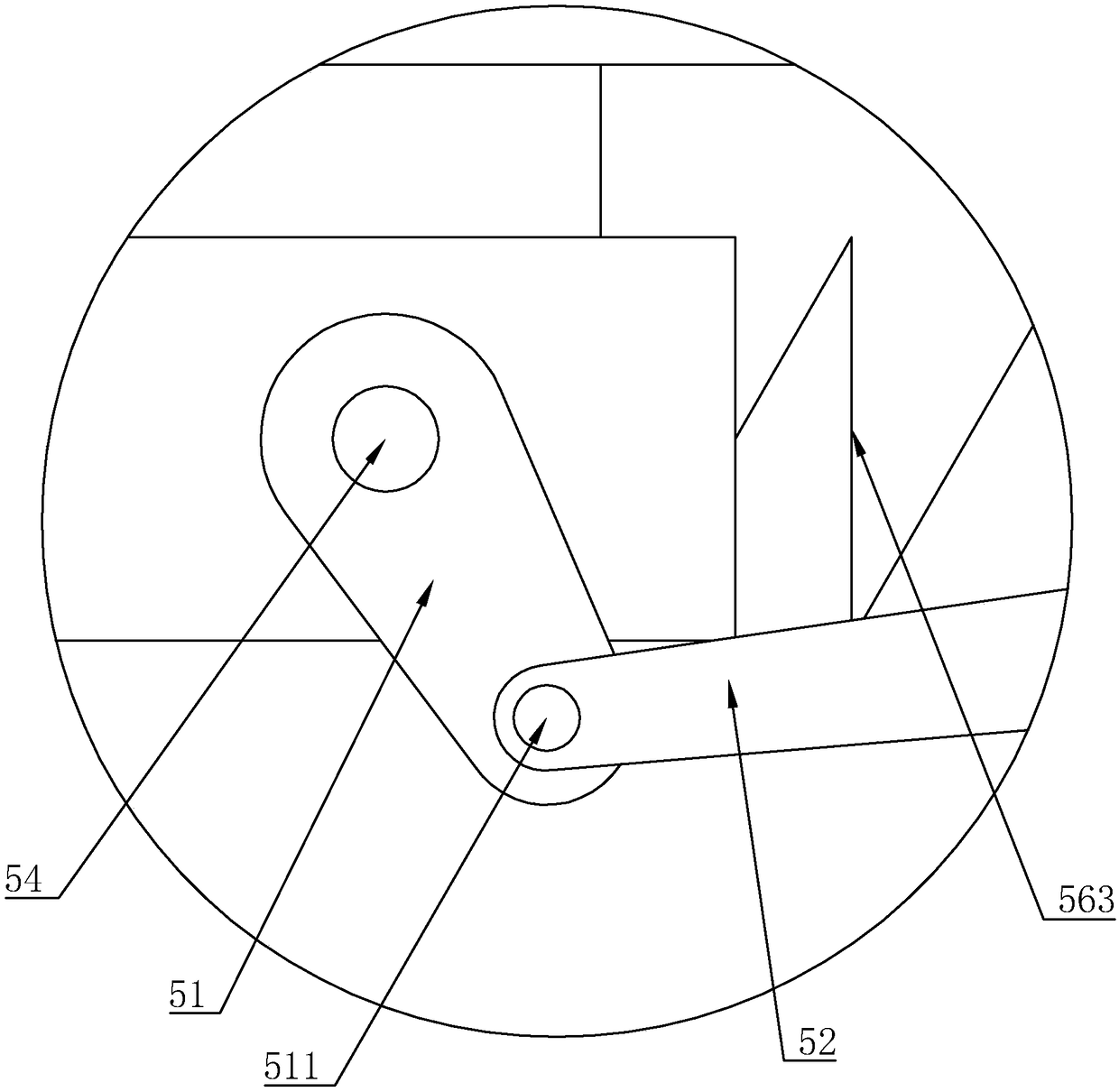
[0020] refer to figure 1 , figure 2 , image 3 As shown, a thermal deicing device for substation equipment in this embodiment includes a casing 1 and a substation group, the substation group is arranged in the casing 1, and the casing 1 is provided with an antifreeze device, and the antifreeze device It includes a heating assembly 4, a shaking device 2 for shaking off snow to prevent snow accumulation, and a blowing device 3 for blowing away falling snow. The blowing device 3 and the heating assembly 4 are all arranged in the casing 1, and the shaking The device 2 is linked with the blowing device 3 to drive the blowing device 3 to blow the snow away. The shaking device 2 includes the first vibration plate 21, the second vibration plate 22 and the first vibration plate 21 and the second vibration plate 22 for driving the first vibr...


PUM


Abstract

A thermodynamic de-icing device for transformer equipment includes a housing and a substation, A subset is disposed within the housing, An anti-freezing device is arranged on that house and includes aheating assembly, A shake device and a blow device, A shake device includes a first shock plate, a second shock plate and a shock assembly, Thefirst shock plate and the second shock plate are provided, so that the outer snow falls on the first and second panels, A first vibration plate is driven to slide on the upper side of the housing by the vibration assembly, the second shock plate slides reciprocally on the upper side of the first shock plate, The snow falling on the first shock plate and the second shock plate does not accumulate, and the heating assembly helps melt the snow and furtherassists in clearing the snow, and the first shock plate and the second shock plate can push each other so as to loosen the snow with a thicker thickness, thereby realizing the effect that a single shock plate cannot achieve.

Description

technical field [0001] The invention relates to the field of power equipment, and more specifically relates to a thermal deicing device for power transformation equipment. Background technique [0002] With the rapid development of my country's economy and the improvement of people's living standards, it is becoming more and more important to ensure the safe operation of the power grid. However, in some cities with low temperature all year round, rain, snow and freezing weather often cause great damage to substation equipment, and will bring hidden dangers of frost cracking to coupling capacitors, CTs, busbar pillar porcelain bottles and other equipment in substations. If the equipment is greatly affected, it will affect the power supply of a large area, which will have a great impact on people's lives and even cause serious losses. [0003] Among them, the transformer on the road will also be affected by ice coating and low temperature, which will cause the internal substa...

Claims


Application Information

Patent Timeline
IPC IPC(8): H02B3/00
CPCH02B3/00
Inventor 周婕张一池胡缤幻吴伟银
Owner WENZHOU ELECTRIC POWER DESIGN
Learn More