
Line fault region identification method

A line fault and area identification technology, applied in the electrical field, can solve the problems of long delay, no current limiting reactor boundary, weakened DC line fault characteristics, etc., and achieves strong resistance to transition resistance, low communication requirements, and fast action speed. Effect

Active Publication Date: 2018-12-21
ELECTRIC POWER RESEARCH INSTITUTE, CHINA SOUTHERN POWER GRID CO LTD +1
View PDF8 Cites 6 Cited by
  • Summary
  • Abstract
  • Description
  • Claims
  • Application Information

AI Technical Summary

Problems solved by technology

[0004] Since the different lines of the parallel multi-terminal hybrid DC system are directly connected, there is no current-limiting reactor boundary at both ends of the DC line in the DC grid, so the DC grid protection principle based on MMC cannot be directly applied
However, the principle based on longitudinal DC differential requires the exchange of synchronous current information between stations, and when the line is long, in order to avoid misjudgment of external faults, the delay time that needs to be set is also relatively long
If the line is configured with fast traveling wave protection, after the protection operates, the fault characteristics of the DC line will weaken, and the discrimination method based on the principle of DC differential will be difficult to reliably locate the fault line

Method used


Image

  • Line fault region identification method
  • Line fault region identification method
  • Line fault region identification method

Examples


Embodiment 1

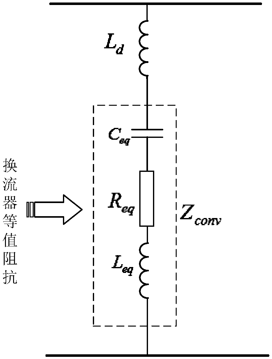
[0052] Such as Figure 1-10 As shown, since the transfer function of the T zone is affected by many parameters, including the equivalent resistance R of the converter eq , equivalent inductance L eq , Equivalent capacitance C eq Peace wave reactor L d . The following will analyze each influencing factor one by one.

[0053] Converter equivalent inductance L eq = 2L 0 / 3 depends on the inductance L of the bridge arm of the converter 0 , so the equivalent inductance of the T area is determined by the smoothing reactor L d It is determined together with the inductance of the bridge arm; the equivalent capacitance C in the T area eq =6C 0 / N is determined by the submodule capacitance C 0 It is determined together with the number of sub-modules N; the equivalent resistance R in the T area eq = 2R arm / 3 is determined by the equivalent resistance of the bridge arm. However, the parameters corresponding to different projects are different, but the parameters are all with...


PUM


Abstract

The invention discloses a line fault region identification method. The line fault region identification method comprises the following steps of calculating equivalent impedance Zeq of a T region; calculating current T region transfer functions on the non-fault side and the fault side of the T region when a line suffers from a fault, then obtaining an amplitude-frequency characteristic curve, and thereby determining the number J of layers of wavelet transform corresponding to a reduced frequency band; giving an initial value to a fault region judgment start setting value delta set1, wherein themaximum value of T region fault standard energy difference is delta EJset; measuring and working out line mode currents IL and IR; judging whether the fault region judgment protection needs action ornot; measuring and working out T region standard energy difference delta EJ; and by judging the relation between the standard energy difference delta EJ and the maximum value delta EJset, and then judging a fault region. According to the method, the difference of the fault transient state current energy on the two sides of the T region are extracted through wavelet transform according to the cutting-down effect to the low-frequency component in the fault transient state current energy by the T region, and quick and reliable identification of a fault position can be realized, so that fault region judgment is further realized by integrating fault direction position of each T region.

Description

technical field [0001] The invention relates to the field of electrical technology, in particular to a fault area identification method for a parallel multi-terminal hybrid high-voltage direct current transmission line. Background technique [0002] At present, the centralized feed-in of multi-circuit DC is easy to cause commutation failure of multi-circuit DC system, which has a serious impact on the safety and stability of AC-DC hybrid grid, and multi-terminal hybrid DC transmission technology is an effective technical means to solve the above problems one. For example, the UHV multi-terminal hybrid direct current transmission system that China Southern Power Grid plans to put into operation in 2020 - the Wudongde power transmission Guangdong Guangxi direct current transmission project. [0003] The DC overhead line is the component with the highest failure probability in the DC system, so the protection of the DC line is particularly important. In fact, the configuratio...

Claims


Application Information

Patent Timeline
Patent Type & Authority Applications(China)
IPC IPC(8): G01R31/08
CPCG01R31/085G01R31/088
Inventor 李明郭铸黄伟煌曹润彬刘涛李岩许树楷张坤李海锋梁远升王钢
Owner ELECTRIC POWER RESEARCH INSTITUTE, CHINA SOUTHERN POWER GRID CO LTD
Learn More