
Simulation test piece and simulation design method for blade root portion of turbine

A simulation test and impeller technology, applied in the testing of mechanical components, testing of machine/structural components, testing of elasticity, etc., can solve the problem of scarcity of blade root simulation test piece design, and achieve the effect of facilitating machining

Active Publication Date: 2018-12-21
BEIHANG UNIV
View PDF10 Cites 11 Cited by
  • Summary
  • Abstract
  • Description
  • Claims
  • Application Information

AI Technical Summary

Problems solved by technology

At present, the design of blade root simulation test pieces is very scarce

Method used


Image

  • Simulation test piece and simulation design method for blade root portion of turbine
  • Simulation test piece and simulation design method for blade root portion of turbine
  • Simulation test piece and simulation design method for blade root portion of turbine

Examples


Embodiment Construction

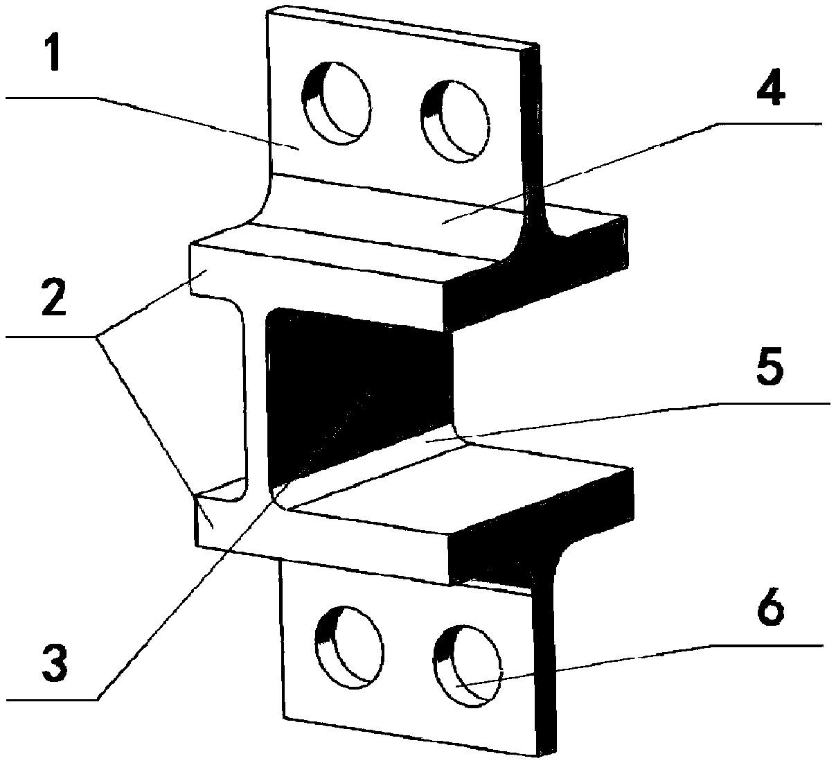
[0020] Such as figure 1 As shown, the simulated test piece involved in the present invention is composed of two upper and lower loading sections 1 , a pair of parallel metal plates 2 and a vertical metal plate 3 . The loading section 1 is located at both ends of the simulated test piece, perpendicular to the parallel metal plate 2, and connected by the transition fillet 4 of the loading section; the vertical metal plate 3 is located between the two parallel metal plates 2, and has a certain distance from the central axis of the loading section 1. Deviating, connected by the transition fillet 5 of the test section. Side-by-side pin holes 6 are arranged on the upper and lower loading sections 1 for connecting with the fixture. The loading section 1 and the vertical metal plate 3 are perpendicular to each other. Among them, the vertical metal plate 3 simulates the turbine blade, and the transition fillet 5 of the test section simulates the root of the blade, which is the observ...


PUM


Abstract

The invention relates to a simulation test piece and a simulation design method for a blade root portion of a turbine. The method comprises the following steps: (1) simulating the shape of a blade byusing a vertical metal plate in the middle of two parallel metal plates; (2) simulating the structure of the blade root portion by using rounded corners of a connection portion of the vertical metal plate and the parallel metal plates; and (3) taking the maximum thickness of the blade as the thickness of the vertical metal plate, and ensuring that Von Mises equivalent stress, stress gradient and equivalent strain of the investigated location of the vertical metal plate are the same as that of the investigated point of an actual blade by adjusting an offset distance between the vertical metal plate and the axis, and the fillet radius and tensile load of the root portion of the vertical metal plate.

Description

technical field [0001] The invention relates to a turbine blade root feature simulation part and a design method, and belongs to the technical field of turbine fatigue performance test equipment for aeroengine blades. Background technique [0002] The service conditions of aeroengine blades are harsh (high temperature, high pressure, high speed, gas corrosion, etc.), and the components are subjected to alternating mechanical and thermal loads. The root of the blade bears the tension and bending moment caused by the aerodynamic load and centrifugal load of the blade, and at the same time, it is the part with a sudden change in geometry. The phenomenon of stress concentration is relatively serious, so it is often the position where cracks initiate and propagate. In this context, in order to ensure the safety of the engine blade, it is necessary to carry out a mock test on the root of the blade during the development stage. In order to ensure the correctness of the test result...

Claims


Application Information

Patent Timeline
IPC IPC(8): G01M13/00G01M5/00
Inventor 王荣桥胡殿印赵淼东王西源毛建兴
Owner BEIHANG UNIV
Learn More