
Crane, method for controlling tension of steel wire rope and hydraulic system

A hydraulic system and wire rope technology, which is applied in the field of construction machinery, can solve problems such as low work efficiency and insufficient stability, and achieve the effects of increasing working life, improving force loading, reducing stroke and adjusting time

Active Publication Date: 2012-06-13
ZOOMLION HEAVY IND CO LTD
View PDF7 Cites 17 Cited by
  • Summary
  • Abstract
  • Description
  • Claims
  • Application Information

AI Technical Summary

Problems solved by technology

[0005] The main purpose of the present invention is to provide a crane, a method and a hydraulic system for controlling the pulling force of the steel wire rope, so as to solve the insufficient stability of the telescopic boom crane with the superlift hoisting mechanism in the boom telescoping process in the prior art, and the working low efficiency problem

Method used


Image

  • Crane, method for controlling tension of steel wire rope and hydraulic system
  • Crane, method for controlling tension of steel wire rope and hydraulic system
  • Crane, method for controlling tension of steel wire rope and hydraulic system

Examples


Embodiment Construction

[0035] It should be noted that, in the case of no conflict, the embodiments in the present application and the features in the embodiments can be combined with each other. The present invention will be described in detail below with reference to the accompanying drawings and examples.

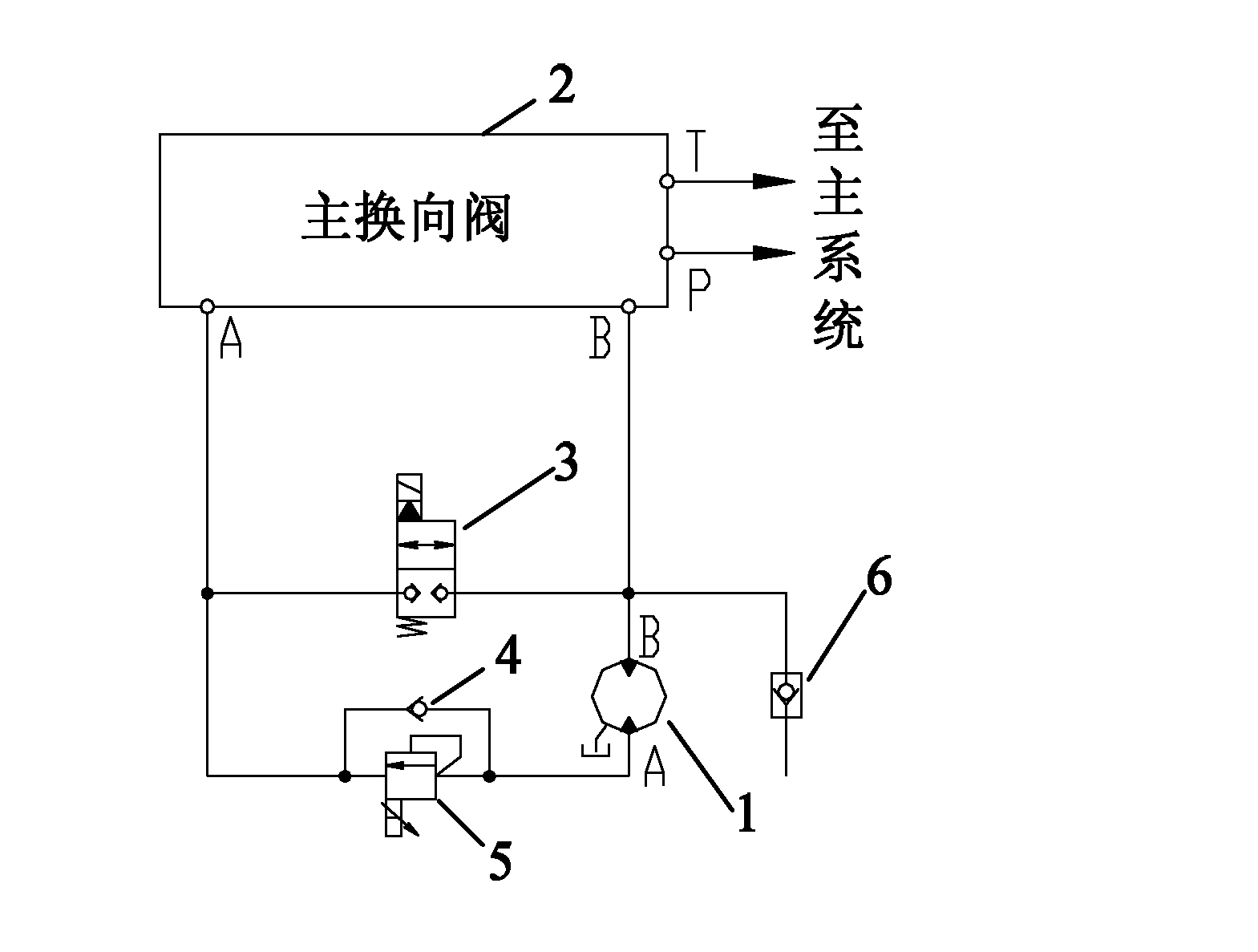
[0036] figure 2 It is a schematic diagram of a basic structure of a hydraulic system for controlling the pulling force of a wire rope according to an embodiment of the present invention. Such as figure 2 As shown, the hydraulic system for controlling the tension of the wire rope in the embodiment of the present invention mainly includes a hydraulic motor 1 , a main reversing valve 2 , a switching valve 3 , a one-way valve 4 , and a back pressure valve 5 . The hydraulic motor 1 is used to output power to the wire rope traction device; the main reversing valve 2 is used to introduce hydraulic oil into the hydraulic system; the back pressure valve 5 is used to provide back pressure to the hydr...


PUM


Abstract

The invention provides a crane, a method for controlling the tension of a steel wire rope and a hydraulic system, and the crane, the method and the system can be used for solving the problems of low stability and low work efficiency of the conventional stretchable arm type crane with a super-lifting winding mechanism during stretching of a lifting arm in the prior art. The hydraulic system comprises a master reversing valve, a switching valve, a check valve, a backpressure valve and a hydraulic motor, wherein the master reversing valve is used for leading hydraulic oil into or out of the hydraulic system; the hydraulic motor is used for outputting power to a traction device of the steel wire rope; a first end of the switching valve is communicated with a first oil outlet of the master reversing valve; the inlet of the check valve is communicated with the outlet of the backpressure valve; a second end of the switching valve is communicated with the second oil outlet of the master reversing valve and a first end of the hydraulic motor; and the inlet of the backpressure valve is communicated with the outlet of the check valve and a second end of the hydraulic motor.

Description

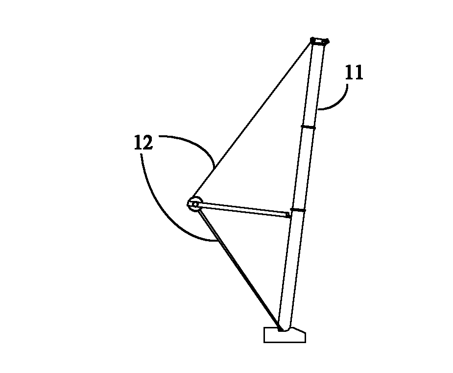
technical field [0001] The invention relates to the technical field of engineering machinery, in particular to a crane, a method for controlling tension of a wire rope, and a hydraulic system. Background technique [0002] Crane is a kind of common construction machinery. With the continuous improvement of production demand, the lifting load of the crane is also increasing. For telescopic boom cranes, in order to increase the overall stability after the boom is stretched out, most of the large telescopic boom cranes are equipped with a superlift winch mechanism. The super-lift winch mechanism is mainly composed of steel wire rope, super-lift winch motor, super-lift reducer and auxiliary hydraulic pressure and control systems. figure 1 is a schematic diagram of the boom of a crane, at figure 1 Among them, 11 is a boom, and 12 is a super lifting wire rope. [0003] In the related art, when the telescopic boom of the crane is stretched out, with the continuous increase of th...

Claims


Application Information

Patent Timeline
Patent Type & Authority Applications(China)
IPC IPC(8): B66C13/20F15B13/02B66C23/693B66C23/72
CPCB66C23/823B66D1/44B66D5/26B66C13/20
Inventor 詹纯新刘权李英智张建军李怀福李义
Owner ZOOMLION HEAVY IND CO LTD
Learn More