A kind of laser self-mixing interferometric measurement device and measurement method

A self-mixing interference and measurement device technology, applied in the field of optical sensing, can solve the problems of expensive output light polarization of electro-optic modulators, small continuous wavelength modulation range, strong fluctuation of output light, etc., and achieve high interference phase detection accuracy, modulation Large scope, low cost effect

Active Publication Date: 2020-06-16
JINAN UNIVERSITY
View PDF10 Cites 0 Cited by
  • Summary
  • Abstract
  • Description
  • Claims
  • Application Information

AI Technical Summary

Problems solved by technology

Among them, the injection current modulation is aimed at the self-mixing interferometer of the semiconductor laser. The wavelength of the laser output light is modulated by changing the injection current of the semiconductor laser. The wavelength continuous modulation range of this method is small, and the output light intensity will be larger when the current is injected. fluctuations, resulting in large measurement errors; external cavity phase modulation is achieved by placing an electro-optic modulator between the laser and the measured target to achieve modulation of the optical phase. This modulation method does not require mechanical moving parts, and the accuracy of displacement measurement is high. EO modulators are expensive and very sensitive to the polarization of the output light, which limits their use in some measurement environments

Method used


Image

  • A kind of laser self-mixing interferometric measurement device and measurement method
  • A kind of laser self-mixing interferometric measurement device and measurement method
  • A kind of laser self-mixing interferometric measurement device and measurement method

Examples


Embodiment 1

[0033] A laser self-mixing interferometry device, comprising a laser 1, a parallel flat crystal 2, a target reflector 3, a rotating platform 4, two intensity-type photodetectors (the first photodetector 7 and the second photodetector 11), Half mirror 10, attenuation sheet 12 and corresponding drive and control circuit.

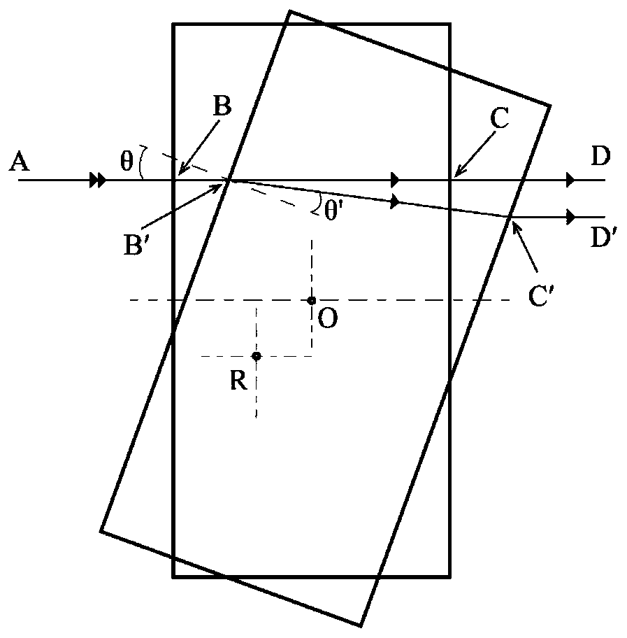
[0034] The front end of the resonant cavity of the laser 1 emits a laser beam, and the laser beam enters the parallel flat crystal 2, exits from the parallel flat crystal 2, is vertically incident on the target reflector 3, and is reflected by the target reflector 3 to form a feedback beam. The feedback beam returns to the resonant cavity of the laser 1 according to the original path, and the feedback beam and the beam in the resonant cavity form self-mixing interference (adjust the attenuation plate 12 to make the interference in a weak feedback state); after the first photodetector 7 detects the resonant cavity of the laser 1 end output light intensity (or p...

Embodiment 2

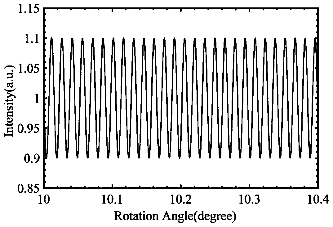
[0039] A method for measuring the micro-displacement of a target reflector using the device of Embodiment 1. First, adjust the above-mentioned optical path so that the laser beam output by the laser 1 is vertically incident on the target reflector 3 through the parallel flat crystal 2, and then passes through the target reflector. 3. The reflection is fed back to the laser cavity of laser 1 according to the original path, forming interference with the laser in the cavity (adjust the attenuation plate 12 to make the interference weak feedback). Then, record the initial position (0°) when the laser beam is vertically incident on the surface of the flat crystal 2, and the rotary table controller 5 drives the rotary platform 4 to rotate within the range of ±90°, changing the optical path of the laser beam inside and outside the parallel flat crystal 2 , to realize the modulation of the self-mixing interference signal, receive the self-mixing interference signal with the photodetect...

Embodiment 3

[0049] figure 1 It is a schematic structural diagram of the laser self-mixing interferometry device disclosed in this embodiment. Laser 1 is a helium-neon laser with an output power of 0.5mW and a wavelength of λ=632.8nm. The parallel flat crystal 2 is a K9 glass flat crystal with a refractive index of 1.5163 and a thickness of 20mm. The target reflector 3 is a plane mirror. After turning on the laser 1 and the computer 9, adjust the optical path so that the laser beam output by the laser 1 is incident on the reflector through the flat crystal, and then reflected by the reflector and fed back to the laser cavity according to the original path to form interference with the laser in the cavity (adjust the attenuation sheet 12, making the interference a weak feedback); then, use the rotating platform 4 to carry the flat crystal 2 to do the rotating motion, and modulate the self-mixing interference signal; use a loudspeaker with a power of 0.25W to carry the target reflector 3, an...


PUM

PropertyMeasurementUnit
thicknessaaaaaaaaaa
refractive indexaaaaaaaaaa

Abstract

The invention discloses laser self-mixing interference measuring device and a measuring method. A rotating platform bears an optical parallel and is placed outside a laser cavity, a laser beam is incident to a target reflector by penetrating the optical parallel and becomes a feedback light after reflection, the feedback light returns to the laser cavity along the same way, the feedback light produces self-mixing interference effect with laser in the cavity, the rotating platform drives the optical parallel to do rotational motion, so as to change optical paths of the laser beam inside and outside the optical parallel and realize modulation on a self-mixing interference signal, the modulated self-mixing interference signal is acquired to a computer by virtue of a photoelectric detector, processing is performed by a software system of the computer to obtain phase information of the interference signal, and multiple physical quantities such as vibration and displacement of the target reflector can be accurately measured. The laser self-mixing interference measuring device disclosed by the invention modulates an external cavity optical path in a way that the optical parallel rotates and constructs a self-mixing interference measuring instrument with large modulation range, high precision, simple operation and low cost.

Description

technical field [0001] The invention relates to the technical field of optical sensing, in particular to a laser self-mixing interference measurement device and a phase modulation measurement method. Background technique [0002] The self-mixing interference (Self-mixing Interference, SMI) effect refers to the effect that the light wave emitted from the laser is reflected back to the laser cavity by an external object, and interferes with the light wave in the laser cavity. Since the feedback light carries the information of the external object, the output characteristics of the laser are modulated by the object outside the cavity, so that the measurement of the physical quantity of the target object can be realized by using this characteristic. The self-mixing interference system only needs one optical channel, so it has the characteristics of simple structure and compactness; in addition, it is easy to collimate, high sensitivity, and convenient signal detection (both from...

Claims


Application Information

Patent Timeline
Patent Type & Authority Patents(China)
IPC IPC(8): G01B9/02G01B11/02
CPCG01B9/02G01B11/02
Inventor 钟金钢齐攀周博文
Owner JINAN UNIVERSITY
Why Eureka
Try Eureka