
Moisture energy hot pump unit and system thereof

A heat pump unit, water vapor energy technology, applied in heat pumps, refrigerators, compressors, etc., can solve the problems of shortened compressor life, swollen evaporator copper tube, long defrosting time, etc., to improve service life, application-specific Strong performance and good energy saving effect

Pending Publication Date: 2018-12-21
HUNAN DONGYOU WATER VAPOR ENERGY HEAT PUMP MFG CO LTD
View PDF2 Cites 3 Cited by
  • Summary
  • Abstract
  • Description
  • Claims
  • Application Information

AI Technical Summary

Problems solved by technology

[0003] At present, it is difficult for the main engine of the air energy heat pump to adapt to the requirements of efficient operation of the ambient temperature below zero, and its technical obstacles are mainly reflected in:
[0004] (1) A large amount of frost accumulation will weaken the heat transfer performance of the evaporator;
[0005] (2) Frosting hinders the gas flow between the outdoor coils, and the energy loss of the fan increases
[0007] (3) The way of defrosting affects the user experience
[0008] (4) Defrost consumes a lot of energy and takes a long time to defrost
[0009] (5) The central air-conditioning heat pump unit cannot use reverse operation to defrost
[0010] (6) If antifreeze is used as the heat-absorbing medium, the temperature of the freezing point will rise, which will cause the copper tube of the evaporator to freeze and expand from time to time.
[0011] (7) Concentrated antifreeze device consumes too much energy
[0012] (8) The operation of the main engine in a low temperature environment makes it difficult to return oil to the refrigeration oil
[0013] (9) If the temperature of the evaporator is too low, it is inevitable that there will be no liquid shock, which will greatly shorten the life of the compressor

Method used


Image

  • Moisture energy hot pump unit and system thereof

Examples


Embodiment Construction

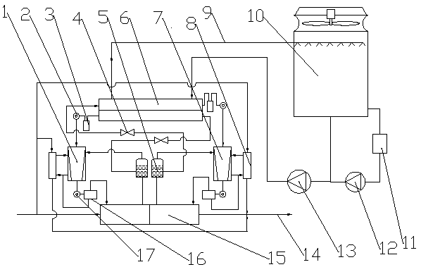
[0036] Such as figure 1As shown, the present embodiment is a dual-compressor heat pump unit and its system, one is a fixed-frequency compressor 7, the other is a variable-frequency compressor 1, the heat source tower antifreeze circulation pump 13 and the circulation pump on the heating medium water pipeline 14 are first When the compressor is started, when the heat pump unit is ready to run, the electric heating is started first to preheat the refrigerating oil. When the preheating makes the refrigerating oil reach a suitable temperature, the variable frequency compressor 1 starts first, and when the power frequency is reached, the fixed frequency compressor 7 is started. Then the refrigerant is compressed into the shell of the segmented shell-and-tube condenser 15. After the heat medium water in the tube side of the condenser absorbs heat, the refrigerant releases latent heat and becomes a liquid refrigerant. The shell-type condenser 15 must pass through the refrigerant outl...


PUM


Abstract

The invention relates to a moisture energy hot pump unit and a system thereof. The system comprises two large parts, wherein a front half part is a high-efficient hot pump host, a rear half part is ahot source tower adaptive to a low-temperature hot source hot pump host, parts forming the low-temperature hot source hot pump host comprise a dual-compressor structure, a combined dried evaporator, acombined segmented condenser, an air supplement and enthalpy addition device, an oil-gas separator, a siphon tank, a refrigeration oil cooling device, an expansion throttling device, a refrigerant inlet angle valve and a refrigerant outlet angle valve, the dual-compressor structure is formed from a variable-frequency compressor and a fixed-frequency compressor, the above main members form the low-temperature hot source host, all parts are combined to form optimal prevention liquid to run efficiently, low ambient temperature heat is absorbed by employing an anti-freezing liquid, a concentration device running efficiently and at a low cost is matched and is a condensation ejector, so that high-efficiency refrigerating under an extremely low-temperature environment is adapted, the system isapplied to a north place at high latitude for warming, traditional boiler for warming can be substituted, and the system is clean, energy-saving and environmental-friendly equipment.

Description

technical field [0001] The invention belongs to refrigeration and heating units, in particular to a water vapor energy heat pump unit and a system thereof. Background technique [0002] Air pollution is becoming more and more serious, greenhouse gas emissions are increasing, the negative effects of greenhouses are becoming more and more prominent, glaciers are melting, and sea level rise has attracted the attention of all mankind. It is an inevitable trend to replace traditional boiler heating with advanced energy-saving and clean energy technologies. The data shows that in 2015 China's total building energy consumption was 857 million tons of standard coal, accounting for 20% of the country's total energy consumption, of which: the energy consumption of public buildings accounted for 341 million tons of standard coal; the energy consumption of urban residential buildings was 3.2 100 million tons of standard coal; the energy consumption of rural buildings is 197 million tons...

Claims


Application Information

Patent Timeline
IPC IPC(8): F25B30/02F25B30/06F25B1/047F25B47/02F25B41/06F25B43/00F25B41/30
CPCF25B1/047F25B30/02F25B30/06F25B43/00F25B47/02F25B41/31
Inventor 黄国和刘小江成剑林
Owner HUNAN DONGYOU WATER VAPOR ENERGY HEAT PUMP MFG CO LTD
Learn More