
Ionic internal mixer

An internal mixer and ion-type technology, which is applied in the field of ion-type mixing internal mixers, can solve the problems of reduced production efficiency, single function, and environmental pollution, and achieve the effects of improving production efficiency, optimizing the working environment, and reducing production costs

Active Publication Date: 2018-12-21
兰溪市旺兴塑胶制品有限公司
View PDF12 Cites 1 Cited by
  • Summary
  • Abstract
  • Description
  • Claims
  • Application Information

AI Technical Summary

Problems solved by technology

[0002] At present, there are two ways of refining raw rubber, one is the open refining method, and the other is the internal mixing method. From the overall effect, the internal mixing method is better than the open refining method. There are many types of internal mixing on the market. Most of the machines are simple in structure, single in function and consistent in principle. They are roughly divided into the following structures: hydraulic device, extrusion rotating device, cooling device, and control device. The principle of internal mixing is to put softened powder into the internal mixer, and then Put the raw rubber in, use the hydraulic cylinder to squeeze the raw rubber into the internal mixer, start the extrusion rotating device, the extrusion wheel starts to rotate, squeeze, tear and recombine the raw rubber according to the special-shaped structure on it, and extrude The continuous rotation of the wheel can make the softened powder and the recombined raw rubber evenly mixed. However, a large amount of heat will be generated in the process of tearing and recombining the raw rubber, which will cause the temperature in the mixing wall to rise sharply. Temperature will affect the fluidity of rubber, which requires a large amount of water to circulate and cool, which will cause waste of water resources. At the same time, the uniform mixing of softened powder requires long-term rotation of the extrusion wheel, which reduces production efficiency. In addition, the fugitive dust generated during the banburying of the softened powder is easily extruded by the air of the equipment to cause environmental pollution, which is not conducive to the health of the operators. For example, a vacuum mixer provided by the Chinese invention patent application number: 201310525322. The top of the mixing room is equipped with a vacuum device for vacuuming the mixing room. During the working process, the mixing room is automatically vacuumed to prevent the harmful gas in the mixing room from being discharged to the outside and causing pollution, and to prevent the chemical industry in the mixing room. The raw material is oxidized by the outside air to ensure that high-quality products can be produced, but this vacuum effect will cause the added powder to be drawn out, which will affect the performance of the rubber after banburying. Therefore, the invention provides an ionic compound Internal mixer

Method used


Image

  • Ionic internal mixer
  • Ionic internal mixer
  • Ionic internal mixer

Examples


Embodiment

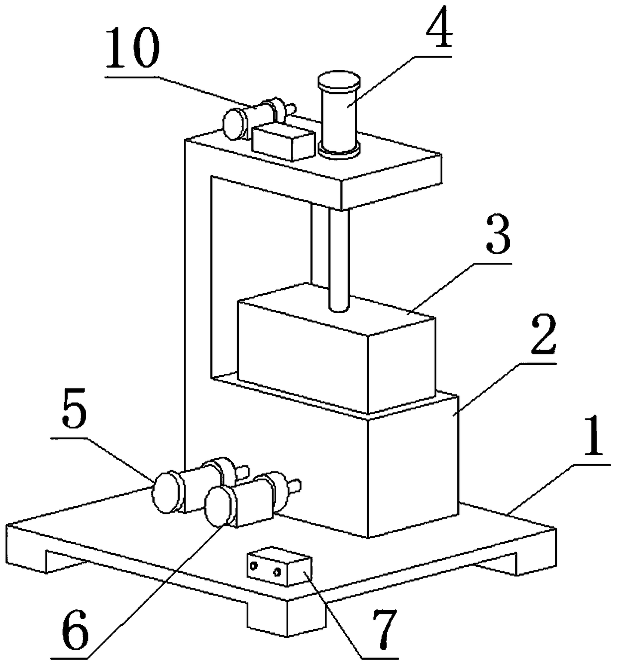
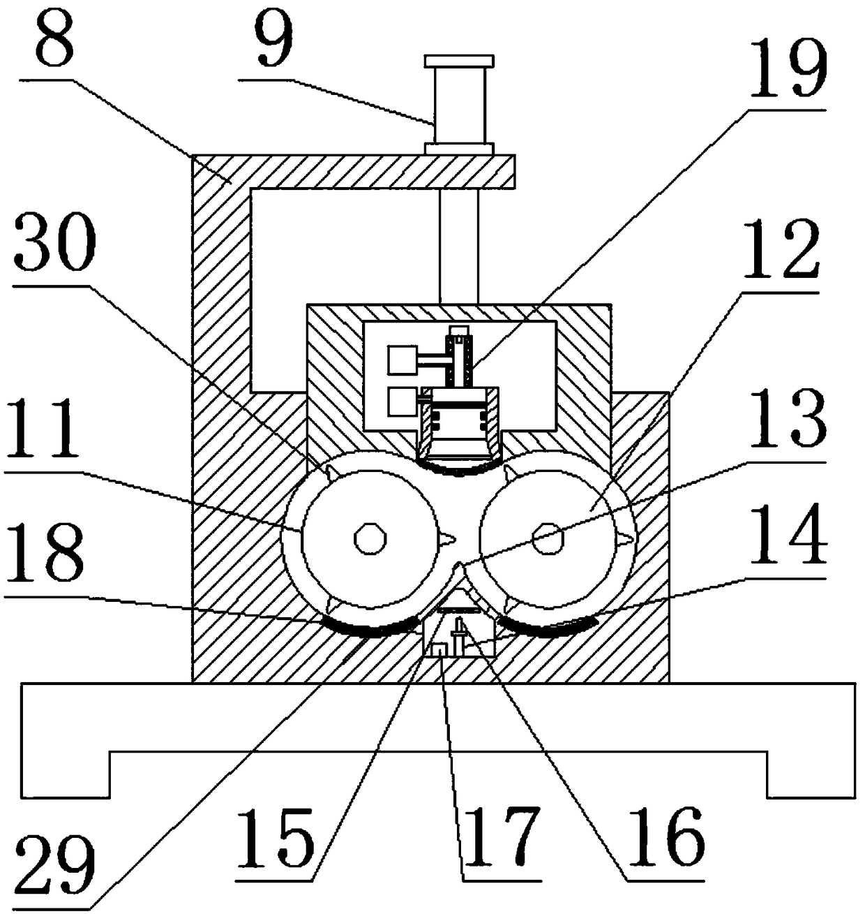
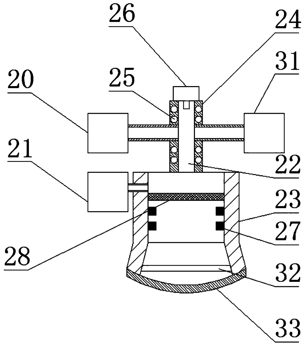
[0022] Examples, see Figure 1~3 , the present invention provides a technical solution:

[0023] An ionic mixing internal mixer, comprising a chassis 1, a banburying chamber 2, a pressure block 3, a hydraulic system 4, a motor unit 5, a motor unit 2 6 and a control box 7, the banburying chamber 2 Set on the bottom frame 1, a support frame 8 is provided on one side of the mixing chamber 2, the hydraulic system 4 includes a hydraulic cylinder 9, a hydraulic motor group 10 and a hydraulic oil tank, and the hydraulic cylinder 9 is set on the support frame 8, one end of the pressure block 3 is connected to the hydraulic cylinder 9, and the other end of the pressure block 3 is sleeved in the banburying chamber 2, and the banburying chamber 2 is provided with a banburying chamber. The mixing chamber is provided with extrusion wheel one 11, extrusion wheel two 12, shear block 13 and cathode arc plate 29. One end connection of the two motor units 6 is arranged on one side of the banb...

Embodiment approach

[0024] As a preferred embodiment of the present invention, the first extrusion wheel 11 and the second extrusion wheel 12 are provided with special-shaped blocks 30 .

[0025] As a preferred embodiment of the present invention, the shear block 13 is provided with wear-resistant threads.

[0026] As a preferred embodiment of the present invention, the hydraulic motor assembly 10 includes an electric motor and a hydraulic motor, and the hydraulic motor is connected to the hydraulic oil tank and the hydraulic oil cylinder 9 through pipelines.

[0027] As a preferred embodiment of the present invention, the control buttons include start button, oil cylinder button, extrusion wheel one button, extrusion wheel two button, propellant button, pressurization button, resistance wire button, discharge button, laser light button and the laser frequency converter knob, the control button is connected to the propellant device 20, the main propellant device 21, the pressurizing device 31, th...


PUM


Abstract

The invention relates to the technical field of raw rubber mixing, an ionic internal mixer comprises a bottom frame, a mixing chamber, a pressure block, a hydraulic system, a first motor unit, a second motor unit and a control box, wherein the mixing chamber is disposed on the bottom frame; a support frame is provided on one side of the mixing chamber; the hydraulic system comprises a hydraulic cylinder disposed on the support frame, a hydraulic motor group and a hydraulic oil tank; one end of the pressure block is connected to a hydraulic cylinder, and the other end of the pressure block is sleeved in a mixing chamber; an extrusion wheel I, an extrusion wheel II, a shearing block and a cathode arc plate are arranged in the mixing chamber; the first motor unit is disposed on one side of the mixing chamber and connected to one end of the extrusion wheel I, and the second motor unit is disposed on one side of the mixing chamber and connected to one end of the extrusion wheel II; a cooling chamber is arranged at the bottom of the shearing block. The equipment is low in energy consumption, high in efficiency, environmentally friendly and beneficial to popularization.

Description

technical field [0001] The invention relates to an ion-type mixing internal mixer, which belongs to the technical field of raw rubber internal mixing. Background technique [0002] At present, there are two ways of refining raw rubber, one is the open refining method, and the other is the internal mixing method. From the overall effect, the internal mixing method is better than the open refining method. There are many types of internal mixing on the market. Most of the machines are simple in structure, single in function and consistent in principle. They are roughly divided into the following structures: hydraulic device, extrusion rotating device, cooling device, and control device. The principle of internal mixing is to put softened powder into the internal mixer, and then Put the raw rubber in, use the hydraulic cylinder to squeeze the raw rubber into the internal mixer, start the extrusion rotating device, the extrusion wheel starts to rotate, squeeze, tear and recombine...

Claims


Application Information

Patent Timeline
Patent Type & Authority Applications(China)
IPC IPC(8): B29B7/20B29B7/22B29B7/82
CPCB29B7/20B29B7/22B29B7/823B29B7/826B29B7/183B29B7/7495
Inventor 李朋
Owner 兰溪市旺兴塑胶制品有限公司
Learn More