


Quick Research
Generate reliable direction feasibility study reports for your R&D in just a few steps.

Technical Q&A
Discover and master advanced knowledge NOW. Basics, ideas, possibilities, all at once.

Find Solutions
As an expert in R&D theories, this can generate solutions to your technical problems instantly.

Evaluate Feasibility
Analyze your overall solution with one click, know your potential R&D risks in advance.

Monitor Landscape
Get weekly tech updates, stay abreast of the latest tech innovations and key insights.
Parallel type flexible wrist mechanism
A parallel and flexible technology, applied in manipulators, program-controlled manipulators, manufacturing tools, etc., can solve the problems of unadjustable rigidity and complex flexible wrist structure, and achieve the effect of long life.
- Summary
- Abstract
- Description
- Claims
- Application Information
AI Technical Summary
Problems solved by technology
Method used
Image

Examples
Embodiment 1
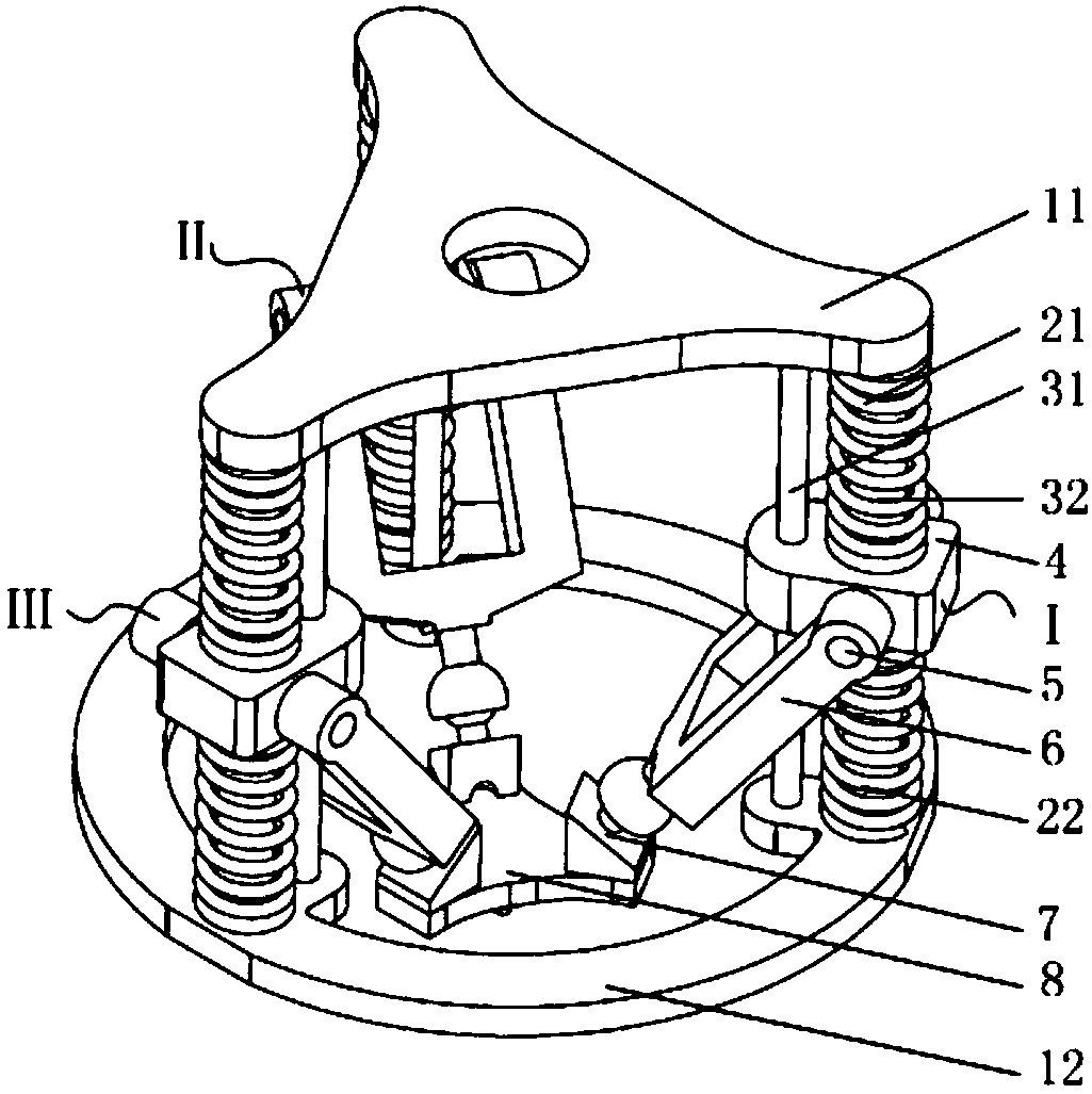
[0017] Such as figure 1 As shown, it is a wrist mechanism with adjustable stiffness, including a fixed platform, a moving platform 8, and the first branch chain I, the second branch chain II, and the third branch chain III; the three branch chains have the same structure, Both include: spring one 21 and spring two 22, slider 4, intermediate connecting rod 6 and kinematic pairs; the fixed platform includes upper sub-platform 11, lower sub-platform 12 and three sets of guide rails fixed between the two sub-platforms The section of the guide rail can be cylindrical or other square shapes; the upper sub-platform 11 and the lower sub-platform 12 are parallel to each other and their central axes coincide; each set of guide rails includes an inner guide rail one 31 and an outer guide rail two 32; The three groups of guide rails are evenly distributed about the central axis of the upper sub-platform, one end of the guide rail is fixedly connected to the upper sub-platform 11, and the ...
Embodiment 2
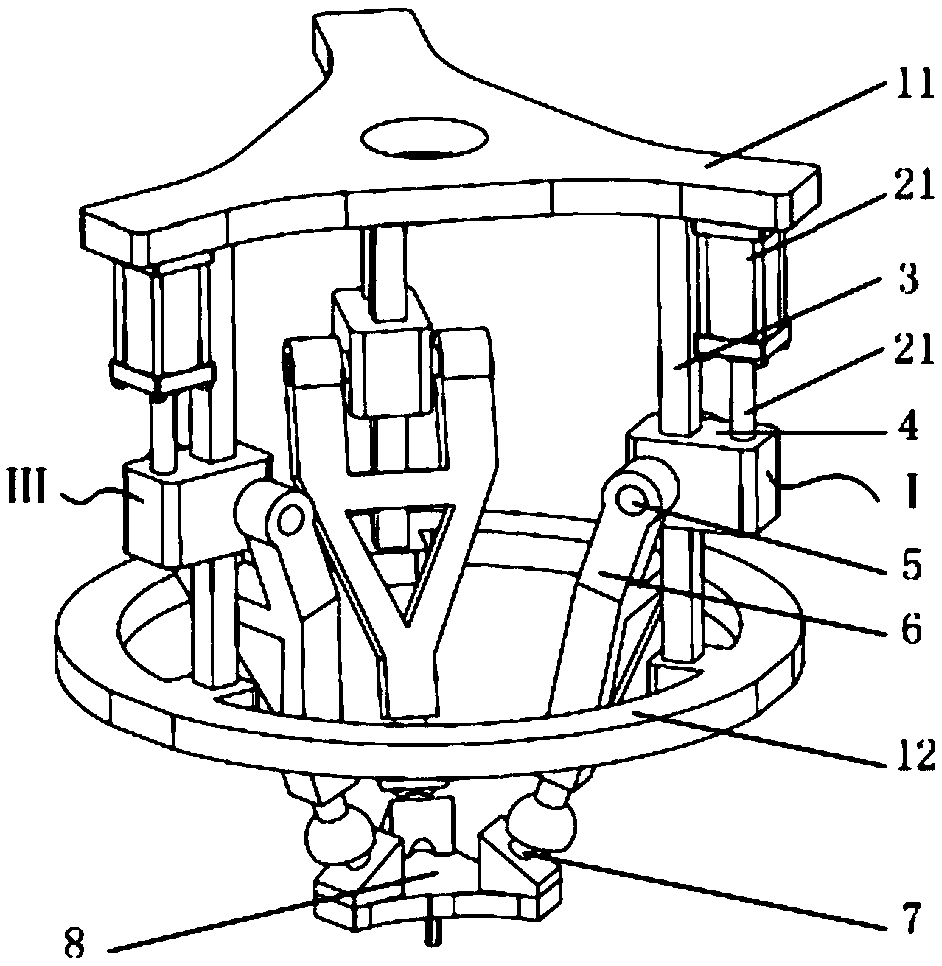
[0019] Such as figure 2 As shown, the difference between the present embodiment and the first embodiment is that the cylinder is used as a linear elastic body to replace the first spring 21 and the second spring 22 in the first embodiment. The cylinder block 21 is affixed to the lower surface of the upper sub-platform 11 , and the piston rod 22 is affixed to the slider 4 . There is only one guide rail 3 of the slide block 4, which is a non-revolving member. In this embodiment, the guide rails of the slider are no longer two, but one, so it cannot be a rotating body such as a cylinder. Certainly, the cylinder body 21 may also be fixedly connected to the slider 4 , while the piston rod 22 is fixedly connected to the lower surface of the upper sub-platform 11 . This embodiment can have the ability to adjust the stiffness, and the adjustment of the stiffness of the mechanism can be realized by changing the air pressure on both sides of the piston in the cylinder. If used with ...
Embodiment 3
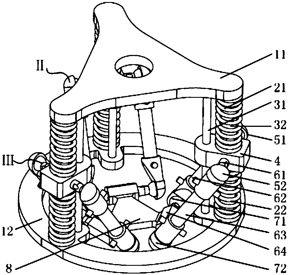
[0021] Such as image 3 As shown, the difference between this embodiment and Embodiment 1 is that the middle link in Embodiment 1 is replaced by a quadrilateral mechanism; the quadrilateral mechanism includes two equal-length upper short links 61 and lower short links 64 And two equal-length left long connecting rods 62 and right long connecting rods 63; the upper short connecting rod 61 is fixed on the slider 4, and the lower short connecting rod 64 is fixed on the moving platform 8; the upper short connecting rod 61 passes through The spherical pair 51 is connected with the left long connecting rod 62, and is connected with the right long connecting rod 63 through the spherical pair 52; the lower short connecting rod 64 is connected with the left long connecting rod 62 through the spherical pair 71, and is connected with the right long connecting rod 63 through the spherical pair 72 connect. During operation, the end effector can passively generate displacement to compensat...
PUM
 Abstract
Description
Claims
Application Information
 - R&D Engineer
- R&D Manager
- IP Professional
- Industry Leading Data Capabilities
- Powerful AI technology
- Patent DNA Extraction
Browse by: Latest US Patents, China's latest patents, Technical Efficacy Thesaurus, Application Domain, Technology Topic, Popular Technical Reports.
© 2024 PatSnap. All rights reserved.Legal|Privacy policy|Modern Slavery Act Transparency Statement|Sitemap|About US| Contact US: help@patsnap.com