Eureka AIR delivers breakthrough ideas for toughest innovation challenges, trusted by R&D personnel around the world.

A method for improving the quality and production efficiency of automatic argon arc welding of system pipelines

A technology of forming quality and production efficiency, applied in the direction of arc welding equipment, welding equipment, welding accessories, etc., can solve the problems of long pre-replacement time of argon gas, uneven welding leakage forming, hidden dangers of redundant materials, etc., and shorten the argon gas flow The effect of saving time, improving the qualification rate of welds, and convenient height positioning

Active Publication Date: 2020-09-04
SHANGHAI INST OF SPACE PROPULSION
View PDF6 Cites 0 Cited by
  • Summary
  • Abstract
  • Description
  • Claims
  • Application Information

AI Technical Summary

Problems solved by technology

[0002] The traditional titanium alloy gas cylinder gas replacement method realizes argon protection on the nozzle and the back of the system pipeline. The argon pre-replacement takes a long time, and the quality of the weld is unstable. Oxidation of the back of the weld often occurs, and the quality of the weld cannot meet the Q / Fc0608 Class I requirements
The formation of solder leakage is uneven, and the oxide particles of solder leakage cause redundant hidden dangers

Method used


Image

  • A method for improving the quality and production efficiency of automatic argon arc welding of system pipelines
  • A method for improving the quality and production efficiency of automatic argon arc welding of system pipelines
  • A method for improving the quality and production efficiency of automatic argon arc welding of system pipelines

Examples


Embodiment Construction

[0055] The present invention will be described in detail below in conjunction with specific embodiments. The following examples will help those skilled in the art to further understand the present invention, but do not limit the present invention in any form. It should be noted that those skilled in the art can make several modifications and improvements without departing from the concept of the present invention. These all belong to the protection scope of the present invention.

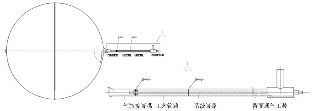
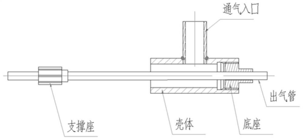
[0056] Such as Figure 1 to Figure 12 As shown, a method for improving the quality and production efficiency of automatic argon arc welding of system pipelines provided according to the present invention includes the following steps:

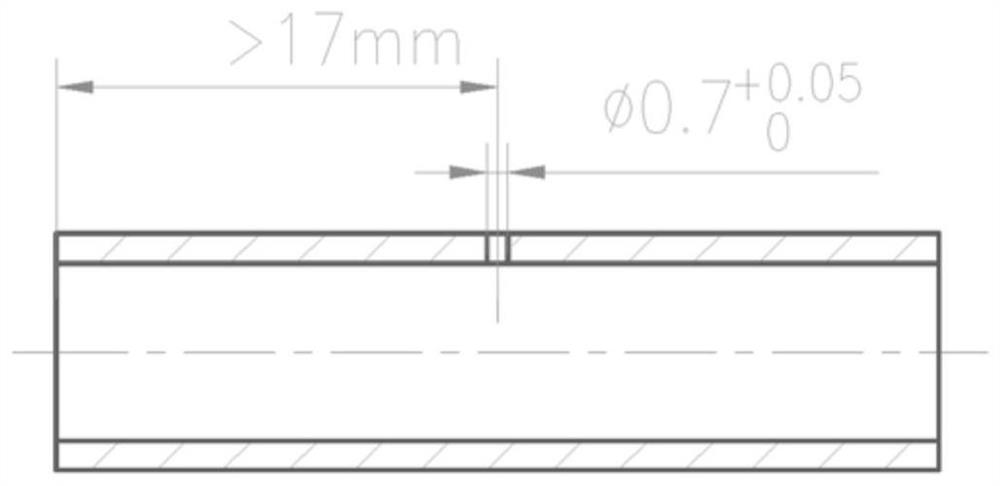
[0057] Step 1: process small holes of Φ0.7mm in the process conduit;

[0058] Step 2: Degreasing the inner wall and surface of process pipes, gas cylinder nozzles and system piping;

[0059] Step 3: Dry the parts to be welded or dry them with hot air;

[0060] St...


PUM


Abstract

The invention provides a method for improving the automatic argon arc welding forming quality and production efficiency of a system pipeline. The method comprises the following steps that a process small hole is machined in a process guide pipe; the process guide pipe, a gas cylinder connecting nozzle and the system pipeline are subjected to oil removal, drying and grinding; automatic argon arc welding is carried out on the gas cylinder connecting nozzle and the process guide pipe, and automatic argon arc welding is carried out on the system pipeline and the process guide pipe; automatic argonarc welding is carried out to block the process small hole in the process guide pipe; sealing detection is carried out on a system pipeline weld joint and a process pipeline plug hole welding spot. According to the method for improving the automatic argon arc welding forming quality and production efficiency of the system pipeline, the argon arc welding quality and efficiency of the titanium alloy gas cylinder connecting nozzle and the system pipeline are solved, the problem of back ventilation protection is solved, a traditional gas cylinder is long in gas exchange period, a process pipelineback ventilation tool is adopted, only needs to be used for 10 minutes, the former efficiency of automatic argon arc welding back ventilation welding of the titanium alloy gas cylinder connecting nozzle of a spaceflight aircraft and the system pipeline is improved, the welding process and the welding process parameters are optimized, and the accurate control of the forming quality of the weldingseam is realized.

Description

technical field [0001] The invention relates to the automatic argon arc welding of the nozzle of the titanium alloy gas cylinder of the aerospace vehicle and the system pipeline, in particular, it relates to a method for efficiently realizing partial argon gas protection on the back of the pipeline and precisely controlling the welding quality of the automatic argon arc welding seam of the titanium alloy pipeline and production efficiency methods. Background technique [0002] The traditional titanium alloy gas cylinder gas replacement method realizes argon protection on the nozzle and the back of the system pipeline. The argon pre-replacement takes a long time, and the quality of the weld is unstable. Oxidation of the back of the weld often occurs, and the quality of the weld cannot meet the Q / Fc0608 Class I requirements. Weld leaks are formed unevenly, and solder leak oxide particles cause excess hidden dangers. [0003] According to the requirements of the pressure-bea...

Claims


Application Information

Patent Timeline
Patent Type & Authority Patents(China)
IPC IPC(8): B23K9/167B23K9/32
CPCB23K9/167B23K9/32
Inventor 刘泽敏林忠刘生建唐磊包海涛于康孙亚非周滨
Owner SHANGHAI INST OF SPACE PROPULSION
Why Eureka
Eureka Blog
Learn More