Stirring structure and stirring type slurry energy storage device

An energy storage device, stirring technology, applied in transportation and packaging, chemical/physical/physical chemical processes of energy application, mixers, etc., can solve the problems of blocked flow channels and diaphragms, reduced energy density, uneven stirring, etc.

Inactive Publication Date: 2018-12-21
CENT SOUTH UNIV
View PDF4 Cites 2 Cited by
  • Summary
  • Abstract
  • Description
  • Claims
  • Application Information

AI Technical Summary

Problems solved by technology

However, installing an ultrasonic transmitter on the casing not only has the problem of uneven stirring, but also the ultrasonic wave will have a greater destructive effect on the SEI film of the negative electrode material.
[0005] At the same time, there is a contradiction between the fluidity of the suspension and the solid content of the suspension in the prior art. To increase the overall energy density, the solid content of the electrolyte needs to be increased, but this will deteriorate the fluidity of the electrolyte. If the solid content Lower, not only the energy density is greatly reduced, but also the overall conductance of the electrode is lower, which will cause greater polarization during the reaction process, etc.
Secondly, the stability of the suspension is difficult to guarantee, and it is very easy to form local settlement, blocking the flow channel and diaphragm, which greatly increases the difficulty of equipment design and manufacture
However, if the slurry is completely still during the working process, the electrochemical environment of the active material in different regions of the electrode will be quite different, which will lead to increased polarization of the device and possible dendrite problems.

Method used


Image

  • Stirring structure and stirring type slurry energy storage device
  • Stirring structure and stirring type slurry energy storage device
  • Stirring structure and stirring type slurry energy storage device

Examples


Embodiment 1

[0028] This embodiment provides a stirring structure, which includes a chamber, electromagnets 10 arranged at both ends of the chamber, and magnets 9 arranged in the chamber; the electromagnets 10 at both ends are turned on and off Switching, the magnet 9 moves under the action of the magnetic field of the electromagnet 10 .

[0029] The magnet 9 is set as a magnet 9 made of iron, cobalt, nickel or ferrite and other magnetic materials, and the magnet has one or more different diameters, and its diameter ranges from 10 μm to 1 mm.

[0030] In this embodiment, the magnetic field is switched by turning on and off the electromagnets 10 at both ends, so that the magnets 9 run in different directions, so as to achieve the purpose of stirring. Its structure is simple, easy to operate and has good stirring effect.

Embodiment 2

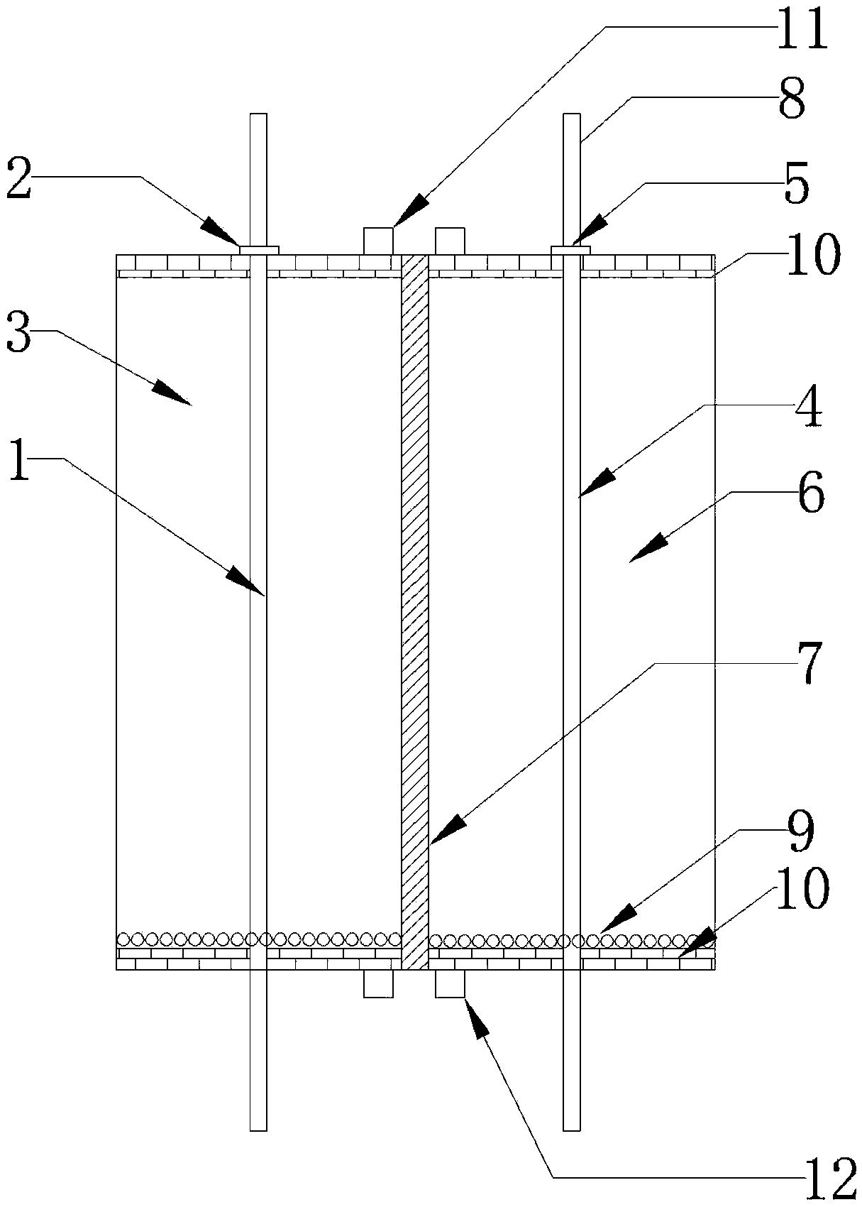
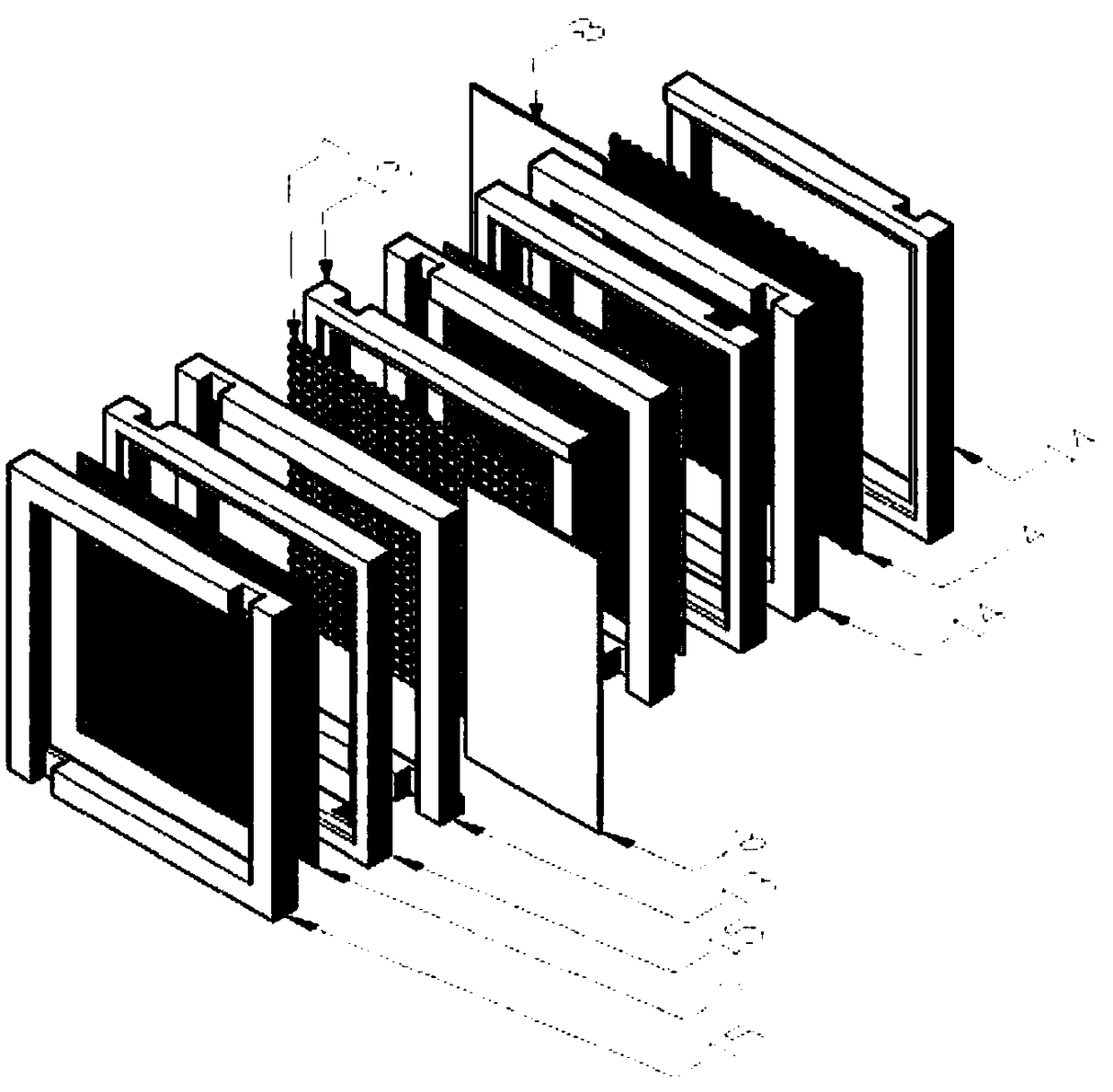
[0032] Such as figure 1 , 2 As shown in and 3, the present embodiment provides a stirring type slurry energy storage device, which includes an electrochemical reactor, and also includes a stirring structure located in the positive electrode chamber 3 and the negative electrode chamber 6 of the electrochemical reactor , the stirring structure includes electromagnets 10 arranged at both ends of the chamber and magnets 9 arranged in the chamber; the electromagnets 10 at both ends are switched on and off according to the driving working system, and the The magnet 9 moves under the action of the magnetic field of the electromagnet 10 to stir the slurry in the chamber.

[0033] In this embodiment, the magnetic field is switched by turning on and off the electromagnets 10 at both ends, so that the magnets 9 run in different directions, so as to achieve the purpose of stirring. The structure is simple, easy to operate and has a good stirring effect; at the same time , intermittent s...

Embodiment 3

[0060] On the basis of Embodiment 2, this embodiment provides a specific stirring type slurry energy storage device, as follows:

[0061] The designed installed capacity is 750kwh, and the designed maximum power is 1mw. The whole device is about 0.8m high and covers an area of ​​2m 2 Left and right, the volume energy density of the device is about 469wh / L, which is basically the same as the current volume energy density of lithium-ion batteries. The device stirs the slurry intermittently during the high-power charging and discharging process, and stirs the slurry after a single charging and discharging cycle.

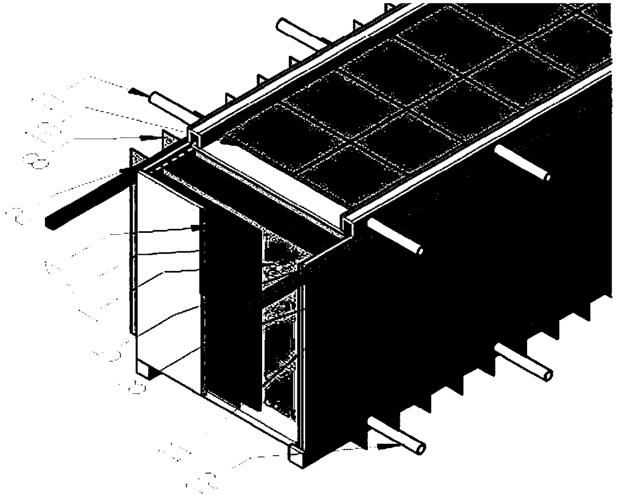
[0062] The internal length and width of the electrochemical reactor of the device are 83cm×200cm×30cm, specifically as image 3 As shown, grooves are engraved on the inside of the upper and lower shells. Among them, the positive current collector 1 is made of 100-mesh metal aluminum mesh, and the negative electrode current collector 4 is made of 100-mesh metal copper...


PUM

PropertyMeasurementUnit
diameteraaaaaaaaaa
diameteraaaaaaaaaa
thicknessaaaaaaaaaa

Abstract

The invention provides a stirring structure. The stirring structure comprises a cavity, electromagnets, and a magnet, wherein the electromagnets are arranged at both ends of the cavity; the magnet isarranged in the cavity; the energizing and deenergizing of the electromagnets are switched, and the magnet is moved under the magnetic field function of the electromagnets. The stirring structure hasthe advantages that the magnetic field is switched by energizing and deenergizing the electromagnets at the two ends, so that the magnet is moved along different directions, thereby reaching the stirring purpose; the structure is simple, the operation is easy, and the stirring effect is better.

Description

technical field [0001] The invention relates to the technical field of slurry energy storage batteries, in particular to a stirring structure suitable for slurry energy storage batteries and a stirring slurry energy storage device with the stirring structure. Background technique [0002] For the electrode manufacturing of lithium-ion batteries, the positive electrode slurry is composed of binder, conductive agent, positive electrode material, etc.; the negative electrode slurry is composed of binder, graphite carbon powder, etc. Semi-solid flow battery is a new type of battery structure that combines flow battery and lithium-ion battery. The specific energy density and other advantages have attracted the attention of academia and industry. . [0003] In the prior art, in order to prevent the occurrence of dead angle and channeling of the suspension in the reactor, and improve the fluidity and power density of the positive and negative suspensions, semi-solid flow batterie...

Claims


Application Information

Patent Timeline
Patent Type & Authority Applications(China)
IPC IPC(8): B01F13/08H01M4/04B01J19/08
CPCB01J19/087H01M4/04B01J2219/00121B01J2219/00051B01F33/452Y02E60/10
Inventor 颜果春刘越盖晓臣李新海王志兴郭华军胡启阳彭文杰王接喜
Owner CENT SOUTH UNIV
Why Eureka
Try Eureka