Synthetic dual-jet spray cooling device based on ultrasonic atomization
A spray cooling and ultrasonic atomization technology, applied in the direction of cooling/ventilation/heating transformation, electrical components, electrical equipment structural parts, etc. compact effect
- Summary
- Abstract
- Description
- Claims
- Application Information
AI Technical Summary
Problems solved by technology
Method used
Image
Examples
Embodiment 1
[0048] In Example 1: a synthetic dual-jet spray cooling device based on ultrasonic atomization includes a liquid supply device and a dual-jet actuator.
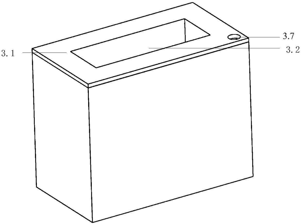
[0049] The double-jet actuator includes a left housing 1.1, a right housing 1.2 and a middle plate 1.3, the inside of the left housing 1.1 and the right housing 1.2 are provided with a concave cavity, and the middle part of the middle plate 1.3 is provided with a concave cavity. Through holes with the same cross section, a vibrating diaphragm 1.4 is arranged in the through hole, and the outer edge of the vibrating diaphragm 1.4 is sealed and connected to the inner wall of the through hole. As in this embodiment, the vibrating diaphragm 1.4 is fixedly installed by a rubber sealing ring Inside the through hole, this ensures a tight seal. The concave cavity inside the left housing 1.1 and the concave cavity inside the right housing 1.2 are respectively arranged on the left and right sides of the middle plate 1.3 and the left hou...
Embodiment 2
[0056] The ultrasonic atomization-based synthetic dual-jet spray cooling device provided in Example 2 also includes a liquid supply device and a dual-jet actuator.
[0057] The dual-jet actuator comprises a left housing 1.1, a right housing 1.2 and a middle plate 1.3. The inner sides of the left housing 1.1 and the right housing 1.2 are provided with concave cavities, and the middle part of the middle plate 1.3 is provided with a through hole with the same cross section as the concave cavity, and a vibrating diaphragm 1.4 is arranged in the through hole, and the vibrating diaphragm The outer edge of 1.4 is sealed and connected to the inner wall of the through hole. As in this embodiment, the vibrating diaphragm 1.4 is fixedly installed in the through hole through a rubber sealing ring, which can ensure the sealing. The concave cavity inside the left housing 1.1 and the concave cavity inside the right housing 1.2 are respectively arranged on the left and right sides of the midd...
PUM
 Abstract
Description
Claims
Application Information
 - R&D Engineer
- R&D Manager
- IP Professional
- Industry Leading Data Capabilities
- Powerful AI technology
- Patent DNA Extraction
Browse by: Latest US Patents, China's latest patents, Technical Efficacy Thesaurus, Application Domain, Technology Topic, Popular Technical Reports.
© 2024 PatSnap. All rights reserved.Legal|Privacy policy|Modern Slavery Act Transparency Statement|Sitemap|About US| Contact US: help@patsnap.com


