Detection and debug system for accelerator control system of automatic driving automobile and platform
A throttle control and automatic driving technology, which is applied in general control systems, control/adjustment systems, test/monitoring control systems, etc., can solve problems such as inconvenient adjustment of throttle control systems, affecting project progress, and prolonging production cycles.
- Summary
- Abstract
- Description
- Claims
- Application Information
AI Technical Summary
Problems solved by technology
Method used
Image
Examples
Embodiment 1
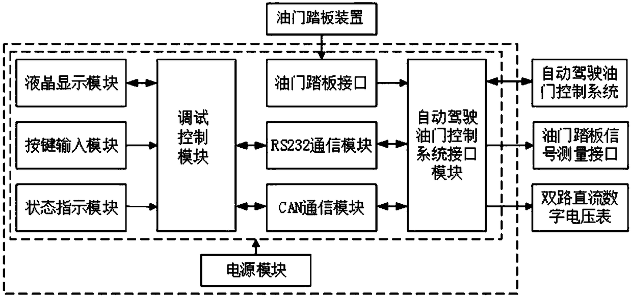
[0051] This embodiment provides a detection and debugging system for the throttle control system of an automatic driving vehicle.
[0052] The detection and debugging system is especially suitable for the throttle control system of an automatic driving vehicle.
[0053] 1. Throttle control system for autonomous vehicles
[0054] Such as Figure 13As shown, the accelerator control system of an automatic driving vehicle includes an accelerator pedal signal switching module, a reference voltage module, an accelerator pedal analog signal generation module, a microcontroller module, a CAN network interface module, a host computer communication interface module and a power supply module;
[0055] The accelerator pedal signal switching module is respectively connected to the accelerator pedal and the motor electronic control module; the engine electronic control module is connected to the electronic throttle body, and the electronic throttle body controls the engine intake; the thro...
Embodiment 2
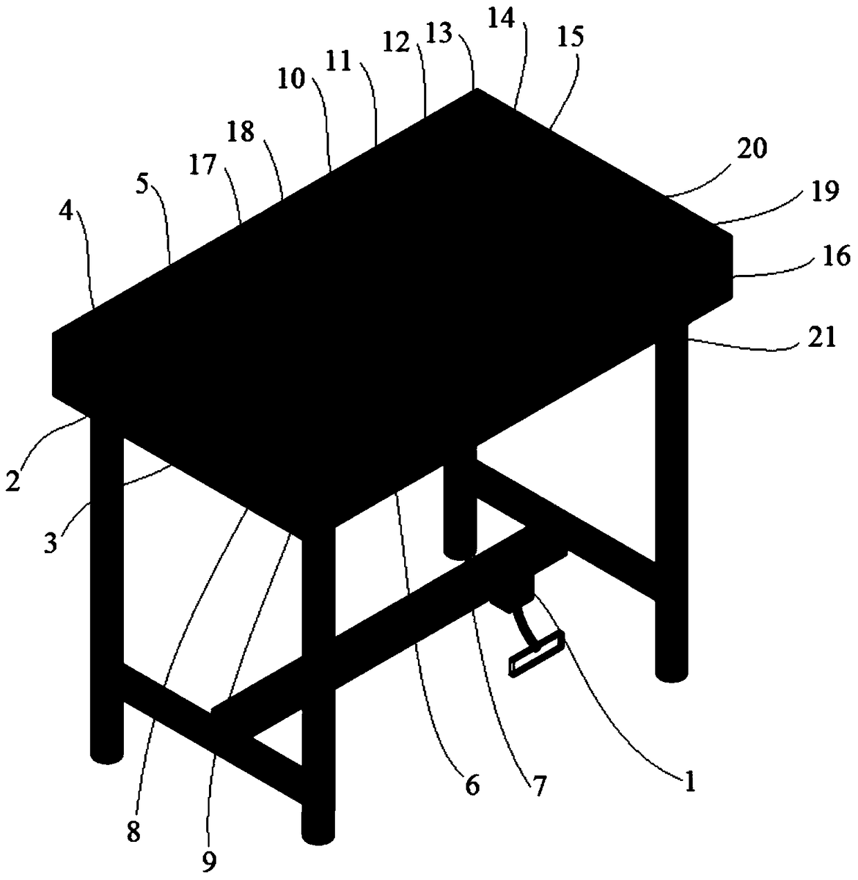
[0119] see figure 1 The difference between this embodiment and Embodiment 1 is that the detection and debugging system is set on a platform.
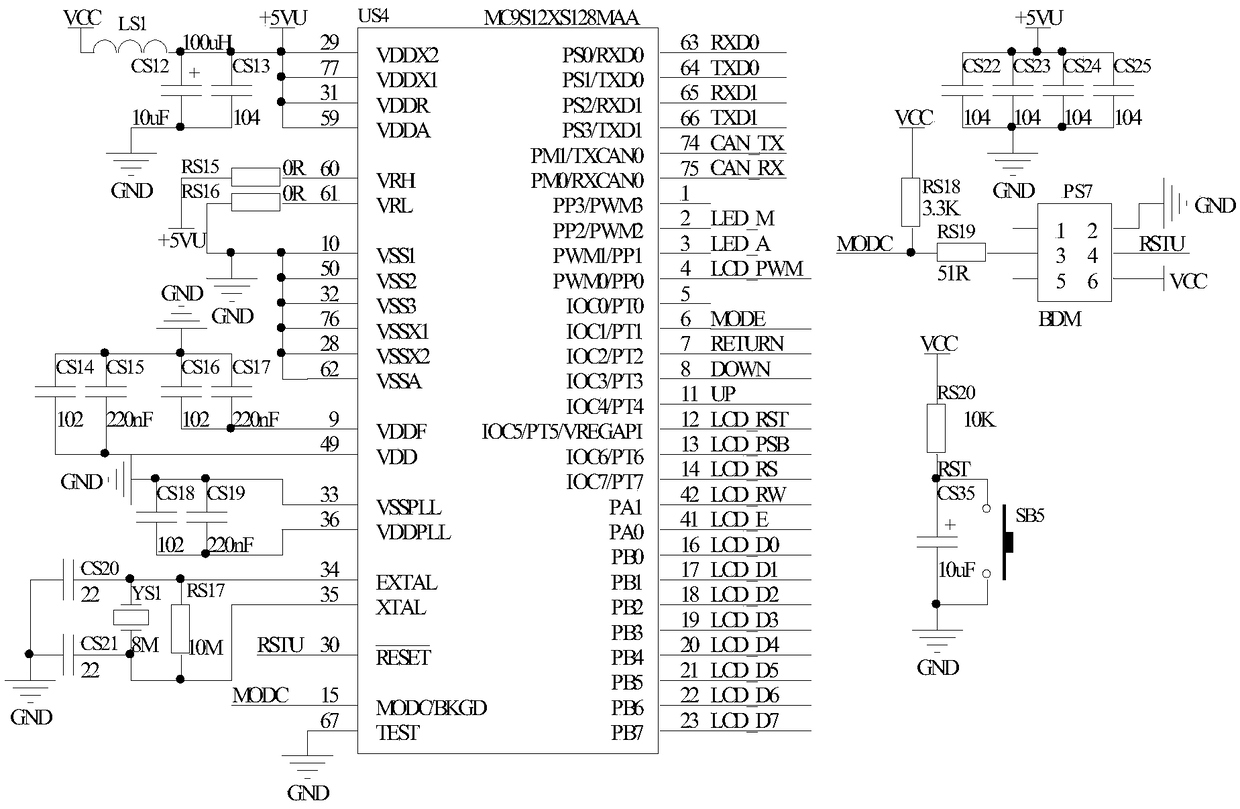
[0120] Specifically, the table top of the platform is provided with a power indicator light 4, a manual mode indicator light 17, and an automatic mode indicator light 18, and the AC power socket 2 and the main power switch 3 are arranged on the side of the platform; the accelerator pedal device 1 includes an accelerator pedal and an accelerator pedal The position sensor is set at the bottom of the platform, and its accelerator pedal position sensor is connected to Figure 9 Accelerator pedal sensor interface PS6 in the middle accelerator pedal interface module; LCD display 5, manual / automatic switch 6, engine electronic control module return data button 7, accelerator increase button 8, accelerator decrease button 9, self-driving car Accelerator control system 10, battery interface 11, accelerator pedal signal interface 12, CAN bus int...
PUM
 Abstract
Description
Claims
Application Information
 - Generate Ideas
- Intellectual Property
- Life Sciences
- Materials
- Tech Scout
- Unparalleled Data Quality
- Higher Quality Content
- 60% Fewer Hallucinations
Browse by: Latest US Patents, China's latest patents, Technical Efficacy Thesaurus, Application Domain, Technology Topic, Popular Technical Reports.
© 2025 PatSnap. All rights reserved.Legal|Privacy policy|Modern Slavery Act Transparency Statement|Sitemap|About US| Contact US: help@patsnap.com


