Centrifugal water pump

A centrifugal and water pump technology, used in non-displacement pumps, non-displacement pumps, rotary piston pumps, etc., can solve the problems of straining the cylinder wall, reducing the efficiency of the plunger pump, and high cost, saving energy. Consumption, improve stability, high self-priming effect

Pending Publication Date: 2018-12-18
GUANGZHOU NENGDONG MECHANICAL & ELECTRICAL EQUIP
View PDF0 Cites 0 Cited by
  • Summary
  • Abstract
  • Description
  • Claims
  • Application Information

AI Technical Summary

Problems solved by technology

Since the cleaning pump is not a closed system, but an open system; its requirement on the flow rate is relatively high. In order to meet this requirement, the volume of the plunger pump needs to be made particularly large, and the cost will be relatively high
[0005] 2. The plunger pump has high requirements on the medium because the liquid directly enters the plunger cylinder. For example, the presence of impurities in the medium will strain the cylinder wall. In the light case, the efficiency of the plunger pump will decrease, and in severe cases, the plunger pump will be locked. or damaged scrap
When the valve is closed to suppress the pressure, the pressure will continue to rise. When it exceeds the set value, the safety valve will open to release the pressure, which will cause serious waste of drive energy consumption.
[0007] However, the existing centrifugal pumps include segmented multistage centrifugal pumps. Although high pressure (high head) can be obtained, due to the general curve of centrifugal pumps, such as figure 1 The pressure curve of the water pump is a sensitive curve. When the pressure is released, that is, when the valve is opened for cleaning, the pressure drops rapidly due to the instantaneous increase of the flow rate, and the pressure of the water outlet has always been obtained by sacrificing the flow rate, so it cannot meet the needs of cleaning the pump.

Method used


Image

  • Centrifugal water pump
  • Centrifugal water pump
  • Centrifugal water pump

Examples


Embodiment Construction

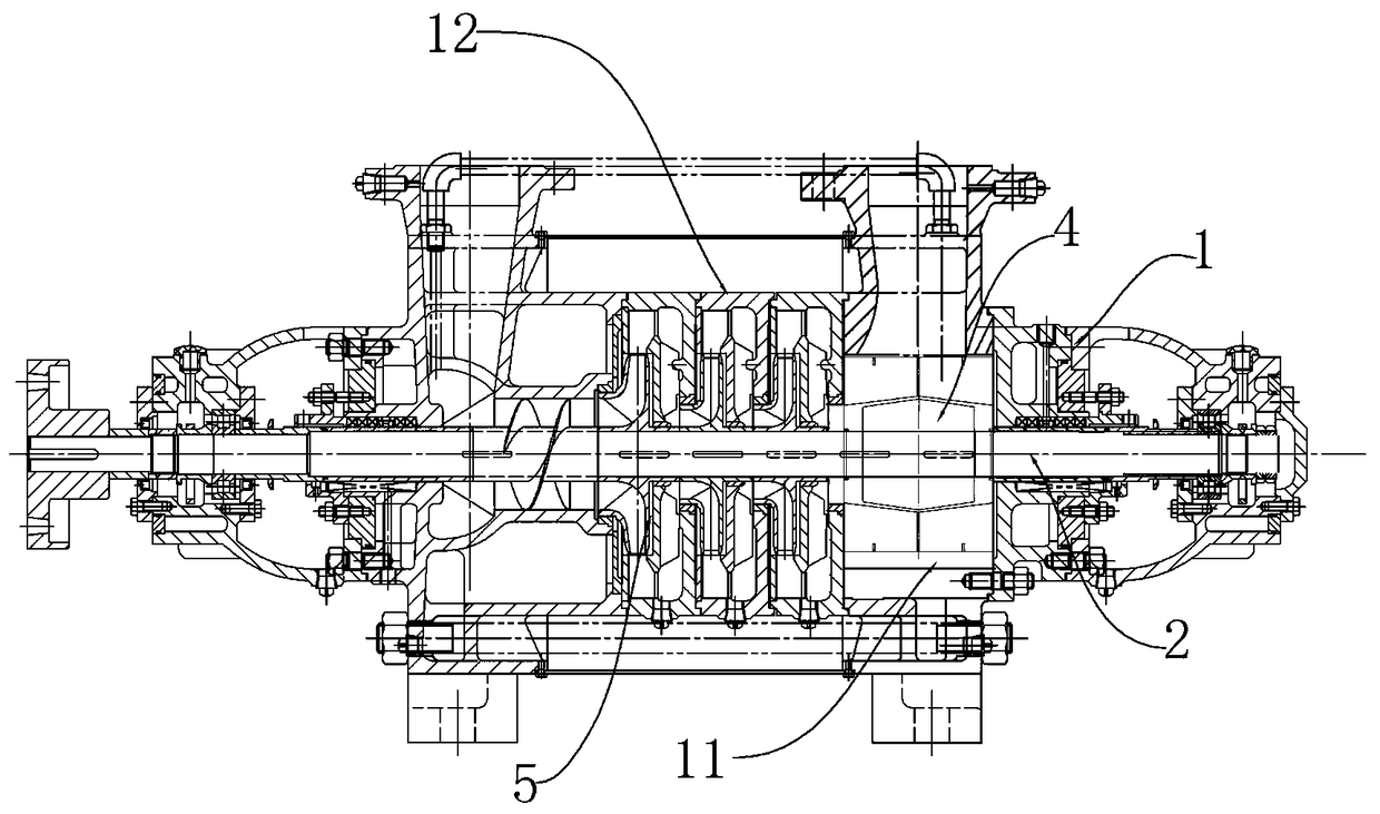
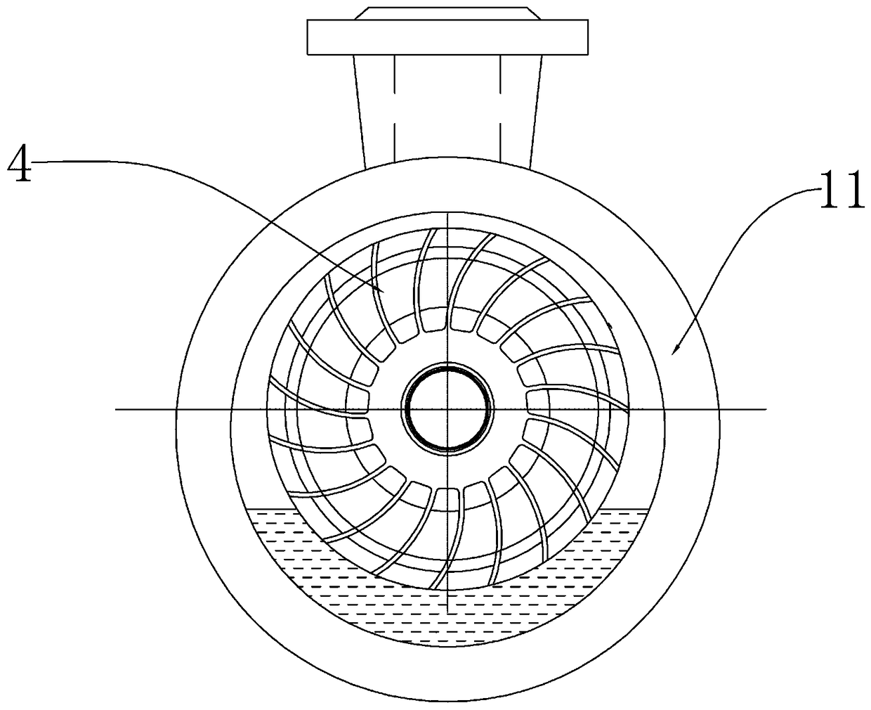
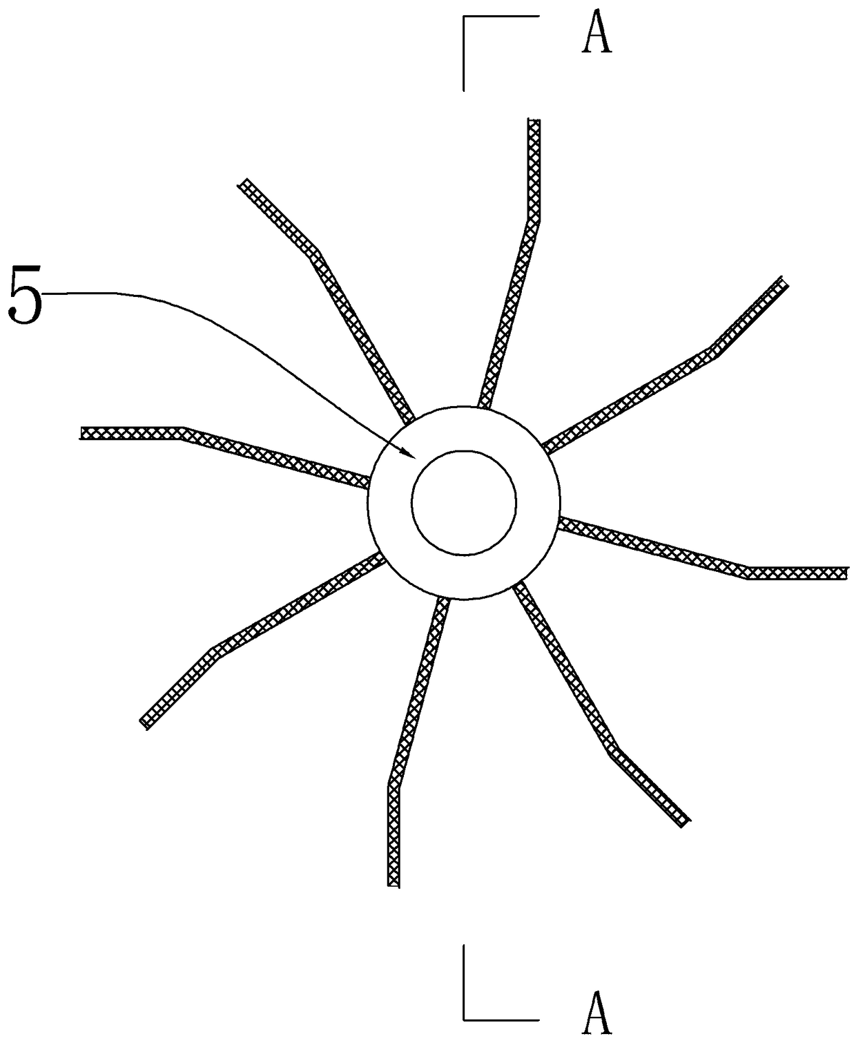
[0017] Such as figure 1 , a centrifugal water pump, comprising a pump casing 1 and a pump shaft 2 rotatably mounted on both ends of the pump casing through bearings, one end of the pump shaft protrudes outside the pump casing, and a connecting part connected to a power input device is installed on the extended section, The connecting part can be a flange 3, such as figure 1 . The pump casing 1 is divided into two connected sections, the front section is the pump volute 11, and the rear section is the segmental pump casing 12; the eccentric rotor 4 with fixed blades is installed in the pump volute; the segmental pump casing is installed with Semi-open tangent impeller 5, the semi-open tangent impeller has a radial structure from the blade to the center of rotation, such as image 3 , Figure 4 .

[0018] In order to improve the efficiency of impeller operation and reduce flow resistance, the impeller can be rotated 15° towards the tangential direction, such as image 3 . ...


PUM


Abstract

The invention discloses a centrifugal water pump. A pump shell of the centrifugal water pump is divided into a front section and a rear section, wherein the front section and the rear section are connected with each other, the front section is provided with a pump volute and the rear section is provided with a segmented pump shell. An eccentric rotor with fixed blades is installed in the pump volute. A semi-open type tangent impeller is installed in the segmental pump shell, and blades of the semi-open type tangent impeller are in a radial structure at the rotation center. The centrifugal water pump has a low flow rate, high pressure and high self-suction capability of a plunger pump, overcomes the defects of an existing centrifugal pump as a high-pressure cleaning pump, fundamentally overcomes the defects of the plunger pump in operation, enables the structure of the centrifugal water pump to be simpler and enables the operation to be more stable, can effectively save the use energy consumption, and improves the efficiency and the application stability, so that the centrifugal water pump can be well applied to high-pressure cleaning equipment.

Description

technical field [0001] The invention relates to a water pump structure, in particular to a centrifugal water pump structure. Background technique [0002] High-pressure cleaning is one of the most economical and environmentally friendly cleaning methods. Existing high-pressure cleaning equipment usually uses a power device to make a high-pressure plunger pump generate high-pressure water, which is jetted to the surface of the object, and dirt, rust, etc. are peeled off and washed away, thereby achieving the effect of cleaning the surface. This cleaning method is widely used in coal, mining, metallurgy, railways, ships and other fields. [0003] The existing high-pressure cleaning equipment, due to the characteristics of the centrifugal water pump, the pressure performance is extremely unstable when the flow rate is guaranteed. When the flow demand of the multi-stage high-pressure centrifugal pump is large, the pressure drops sharply and the cleaning effect is poor. All the...

Claims


Application Information

Patent Timeline
IPC IPC(8): F04D9/04F04D1/06F04D29/22F04D29/42F04C19/00F04C25/02
CPCF04C19/00F04C25/02F04D1/06F04D9/041F04D29/22F04D29/426
Inventor 刘学良李锦泉
Owner GUANGZHOU NENGDONG MECHANICAL & ELECTRICAL EQUIP
Why Eureka
Try Eureka