Pipe gallery anchor core mold pressing and fixing device

A technology for stabilizing devices and anchors, applied in water conservancy projects, artificial islands, sheet pile walls, etc., can solve the problems of affecting the compaction effect, limited length of steel cables, and increasing costs, etc., to achieve reasonable design, convenient use, and cost reduction Effect

Active Publication Date: 2018-12-18
JIANGSU JINMAO TECH DEV
View PDF9 Cites 0 Cited by
  • Summary
  • Abstract
  • Description
  • Claims
  • Application Information

AI Technical Summary

Problems solved by technology

[0002] The underground pipe gallery is used for public tunnels for centralized laying of water, electricity, gas, communication and other municipal pipelines in the city. The existing underground pipe gallery is generally prefabricated with a square structure with openings on both sides. The steel cables are connected and tightened. The length of the steel cables is limited. An anchor groove will be set at the corner of the prefabricated pipe gallery for the connection and tightening of the steel cables. The tightening process is to install an outer mold on one end of the anchor groove. The outer mold is connected to the tail (or head) of the steel cable, the outer mold is provided with a mandrel, the mandrel is tapered outside, the inner ring of the mandrel is set on the steel rope, and the other end of the anchor groove is provided with a support sleeve, The core mold is pressed into the outer mold by the tensioner to tighten it. In the actual use process, there will be two problems. 1. The outer mold is unstable during the pressing process, which will affect the pressing effect; 2. The function of the support sleeve is only as a The support frame of the tensioner is useless after being compressed. There are 3-6 anchoring grooves in each pipe gallery. Thousands of support sleeves are needed to complete a project, which increases the cost and needs to be improved.

Method used


Image

  • Pipe gallery anchor core mold pressing and fixing device
  • Pipe gallery anchor core mold pressing and fixing device
  • Pipe gallery anchor core mold pressing and fixing device

Examples


Embodiment Construction

[0013] The present invention will be further explained below in conjunction with the accompanying drawings and specific embodiments. It should be understood that the following specific embodiments are only used to illustrate the present invention and are not intended to limit the scope of the present invention. It should be noted that the words "front", "rear", "left", "right", "upper" and "lower" used in the following description refer to the directions in the drawings, and the words "inner" and "outer ” refer to directions towards or away from the geometric center of a particular part, respectively.

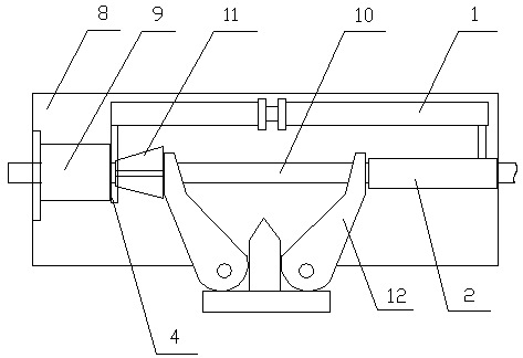
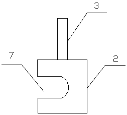
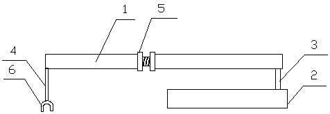
[0014] As shown in the figure, a mandrel pressing and stabilizing device for a pipe gallery anchorage according to the present invention includes an adjustment frame 1, a support block 2, a connecting rod 3, and a limit rod 4. The adjustment frame 1 is divided into two sections, front and rear. , the length adjustment nut 5 is arranged between the front and rear joints, the con...


PUM


Abstract

The invention discloses a pipe gallery anchor core mold pressing and fixing device. The device comprises an adjusting frame, a supporting block, a connecting rod and a limiting rod. The adjusting frame is divided into a front section and a rear section. A length adjusting nut is arranged between the front section and the rear section. The connecting rod and the limiting rod are vertically arrangedat the two ends of the adjusting frame. The lower end of the limiting rod is provided with a clamping groove. The supporting block is connected with the connecting rod. A U-shaped groove is formed inthe inner side of the supporting block. The clamping groove is perpendicular to the space of the U-shaped groove. The central line of the clamping groove and the central line of the U-shaped groove are the same. The adjusting frame and the clamping groove can fix an outer mold, the supporting block can be disassembled and can also serve as a support point, the whole device is reasonable in design, convenient to use, good in fixing effect and capable of being used repeatedly, and the cost is reduced.

Description

technical field [0001] The invention belongs to a construction auxiliary device for a pipe gallery, and in particular relates to a mandrel pressing and stabilizing device for an anchorage tool of a pipe gallery. Background technique [0002] The underground pipe gallery is used for public tunnels for centralized laying of water, electricity, gas, communication and other municipal pipelines in the city. The existing underground pipe gallery is generally prefabricated with a square structure with openings on both sides. The steel cables are connected and tightened. The length of the steel cables is limited. An anchor groove will be set at the corner of the prefabricated pipe gallery for the connection and tightening of the steel cables. The tightening process is to install an outer mold on one end of the anchor groove. The outer mold is connected to the tail (or head) of the steel cable, the outer mold is provided with a mandrel, the mandrel is tapered outside, the inner ring ...

Claims


Application Information

Patent Timeline
Patent Type & Authority Applications(China)
IPC IPC(8): E02D29/045E02D5/74
CPCE02D5/74E02D29/10E02D2250/0007
Inventor 胡峻石斌王万顺朱顺义苏宁
Owner JIANGSU JINMAO TECH DEV
Why Eureka
Try Eureka