


Quick Research
Generate reliable direction feasibility study reports for your R&D in just a few steps.

Technical Q&A
Discover and master advanced knowledge NOW. Basics, ideas, possibilities, all at once.

Find Solutions
As an expert in R&D theories, this can generate solutions to your technical problems instantly.

Evaluate Feasibility
Analyze your overall solution with one click, know your potential R&D risks in advance.

Monitor Landscape
Get weekly tech updates, stay abreast of the latest tech innovations and key insights.
Portable cable hole polisher
A cable hole and portable technology, which is applied in the field of portable cable hole polishers, can solve the problems of complicated structure and excessive weight of cable hole polishing tools, and achieves the effects of light weight, easy operation and lightening of burden.
- Summary
- Abstract
- Description
- Claims
- Application Information
AI Technical Summary
Problems solved by technology
Method used
Image

Examples
Embodiment 1
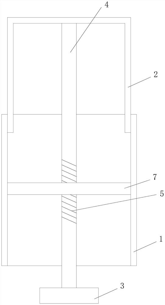
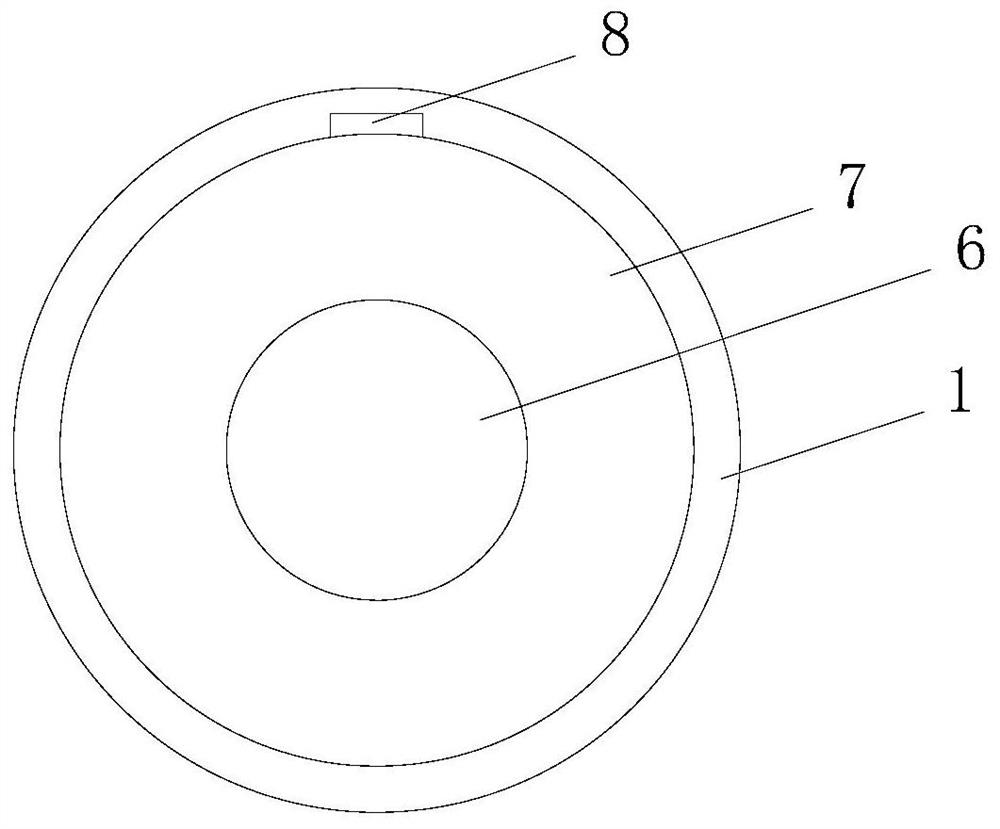
[0021] refer to figure 1 It is the first embodiment of the portable cable hole polisher of the present invention. The portable cable hole polisher includes a fixed cylinder 1, a push cylinder 2, a polishing disc 3 and a driving rod 4. The outer diameter of the fixed cylinder 1 is greater than the inner diameter of the cable hole, so One end of the push cylinder 2 extends into the fixed cylinder 1, and the push cylinder 2 can move axially relative to the fixed cylinder 1, one end of the drive rod 4 is connected with the polishing disc 3, and the other end of the drive rod 4 passes through the fixed cylinder 1 The rear top is inside the pushing cylinder 2, and the middle outer wall of the driving rod 4 is provided with an external thread 5, and the fixed cylinder 1 is provided with an internally threaded hole 6 cooperating with the external thread 5, through which the pushing cylinder 2 relatively fixes the cylinder 1 Moving along the axis drives the polishing disc 3 to rotate a...
Embodiment 2
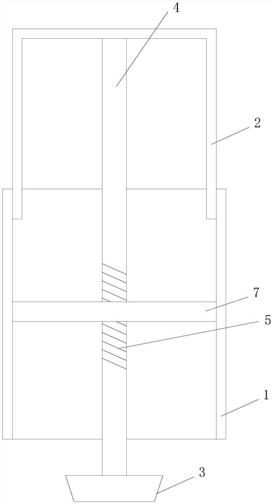
[0028] Such as figure 2 As shown, the difference from Embodiment 1 is that the structure of the polishing disc 3 is different. The polishing disc 3 of the present embodiment is in the shape of a truncated cone, and the larger end face of the polishing disc 3 is fixedly connected to one end of the drive rod 4. The side surface of the polishing disc 3 is polished surface.
[0029] In the initial state, part or all of the polishing disc 3 can be located in the fixed cylinder. When in use, because it is a frustum-shaped polishing disc 3, the front end of the general polishing disc 3 is slightly smaller than the inner diameter of the cable hole. The axis of the fixed cylinder 1 moves, and the driving rod 4 drives the polishing disc 3 to rotate, and at the same time, the polishing disc 3 extends into the cable hole, and the cable hole is polished through the side of the polishing disc 3 . In this embodiment, it is preferable that the maximum diameter of the polishing disc 3 is equ...
PUM
 Abstract
Description
Claims
Application Information
 - R&D Engineer
- R&D Manager
- IP Professional
- Industry Leading Data Capabilities
- Powerful AI technology
- Patent DNA Extraction
Browse by: Latest US Patents, China's latest patents, Technical Efficacy Thesaurus, Application Domain, Technology Topic, Popular Technical Reports.
© 2024 PatSnap. All rights reserved.Legal|Privacy policy|Modern Slavery Act Transparency Statement|Sitemap|About US| Contact US: help@patsnap.com