Cloth blocking mechanism used for clothing embroidery device

A clothing and card cloth technology, applied in the field of clothing manufacturing, can solve the problems of low embroidery efficiency, deformation of embroidered cloth, easy falling off of embroidered cloth, etc., and achieve the effect of improving embroidery efficiency.

Inactive Publication Date: 2018-12-18
HENAN XUMIAN TEXTILE CO LTD
View PDF0 Cites 0 Cited by
  • Summary
  • Abstract
  • Description
  • Claims
  • Application Information

AI Technical Summary

Problems solved by technology

[0004] The purpose of the present invention is to solve the shortcomings of the above-mentioned technical problems. The present invention proposes a card cloth mechanism for garment embroidery devices, which solves the problems of the existing embroidery devices that the embroidered cloth is easy to fall off, the embroidered cloth is deformed, worn, and the embroidery efficiency is low.

Method used


Image

  • Cloth blocking mechanism used for clothing embroidery device
  • Cloth blocking mechanism used for clothing embroidery device
  • Cloth blocking mechanism used for clothing embroidery device

Examples


specific Embodiment approach

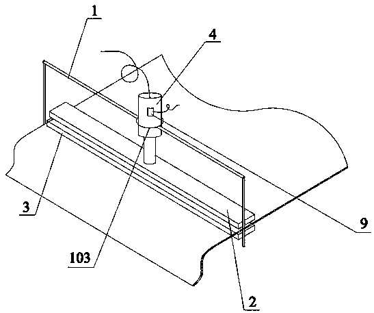
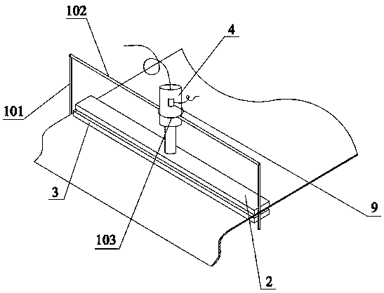
[0020] The card cloth mechanism used for clothing embroidery devices includes a fixed frame 1, an upper pressing plate 2, a lower pressing plate 3 and a cylinder 4, the upper pressing plate 2 is arranged directly above the lower pressing plate 3, and the fixing frame 1 includes a pillar 101 and Cross bar 102, described strut 101 is arranged on the two ends of described lower platen 3 respectively, and described cross bar 102 center is provided with fixed ring 103, and described cylinder 4 upper end is arranged in described fixed ring 103, and lower end and described The upper platen 2 is connected to control the upper platen 2 to move up and down, and cooperate with the lower platen 3 to compress and relax the embroidered cloth; the cylinder 4 is provided with a sensor 9, and the sensor 9 and the cylinder 4 are connected to the control cabinet When in use, a certain sensing distance can be set. When the sensor 9 detects that the embroidery needle reaches the sensing distance, t...


PUM


Abstract

The invention discloses a cloth blocking mechanism used for a clothing embroidery device. The cloth blocking mechanism comprises a fixed frame, an upper pressing plate, a lower pressing plate and an air cylinder, wherein the upper pressing plate is arranged above the lower pressing plate; the fixed frame comprises supporting columns and a cross rod; the supporting columns are separately arranged at the two ends of the lower pressing plate; a fixed ring is arranged on the center of the cross rod; the upper end of the air cylinder is arranged in the fixed ring; the lower end of the air cylinderis connected with the upper pressing plate; both the upper pressing plate and the lower pressing plate are of sandwich structures, and each comprises a bottom plate, a magnet layer arranged on the bottom plate, and a soft layer which is coated outside the magnet layer, the magnet layer comprises a plurality of strip-shaped magnets which are arranged in a spaced mode, a hot circulating pipeline isarranged among the strip-shaped magnets, the hot circulating pipeline comprises a plurality of U-shaped bent tubes, the U-shaped bent tubes are arranged between adjacent two strip-shaped magnets to form a cycle, and a pipeline inlet and a pipeline outlet of the hot circulating pipeline are positioned at the same end. The cloth blocking mechanism solves the problem that embroidered cloth of an existing embroidery device is liable to drop, is liable to deform and wear, and is low in embroidery efficiency.

Description

technical field [0001] The invention relates to the field of garment manufacturing, in particular to a card cloth mechanism used for garment embroidery devices. Background technique [0002] With the development of diversification in the field of clothing manufacturing, embroidery on clothing products is becoming more and more popular. Although artificial embroidery is more delicate, it is inefficient. , is increasingly widely used in various industries. In terms of machinery, it can be divided into frame parts, embroidery parts, color changing parts, frame moving parts, thread hooking parts, thread trimming parts, thread buckling parts, etc. Among them, embroidery parts and shifting parts The frame part is the most important. These two parts are independent and coordinate with each other to complete the embroidery process together. Therefore, it is more efficient to use embroidery machines instead of manual embroidery. [0003] After the embroidery frame of the existing em...

Claims


Application Information

Patent Timeline
Patent Type & Authority Applications(China)
IPC IPC(8): D05C9/04D05C13/00
CPCD05C9/04D05C13/00
Inventor 陈利民
Owner HENAN XUMIAN TEXTILE CO LTD
Why Eureka
Try Eureka