
Zipper head plating hanger and manufacturing method thereof

A technology of electroplating hangers and zipper pullers, which is applied in the electrolysis process, electrolysis components, clothing, etc., can solve the problems of rings being welded crookedly, affecting production efficiency, and unable to guarantee the position accuracy of positioning parts, so as to ensure position accuracy and improve The effect of manufacturing precision

Pending Publication Date: 2018-12-18
石狮市八九机械设备有限公司
View PDF8 Cites 0 Cited by
  • Summary
  • Abstract
  • Description
  • Claims
  • Application Information

AI Technical Summary

Problems solved by technology

[0004] The hanger of the above-mentioned patent is provided with an anode connector so that the coating on the surface of the zipper slider is more uniform, the adhesion is stronger, and the electroplating quality of the zipper slider is improved. However, the ring and the longitudinal beam of this patent are connected by welding. It is difficult to ensure the position accuracy of the ring and the longitudinal beam, and it is easy to appear that the ring is welded crookedly, and the positioning part is also directly welded on the ring, so the position accuracy of the positioning part cannot be guaranteed. Therefore, the above patent hangs a zipper on the automatic hanger Some positioning parts that are not in the right position can not be hung on the zipper head when the head is turned, which seriously affects the production efficiency

Method used


Image

  • Zipper head plating hanger and manufacturing method thereof
  • Zipper head plating hanger and manufacturing method thereof
  • Zipper head plating hanger and manufacturing method thereof

Examples


Embodiment Construction

[0024] The technical solution in the present invention will be clearly and completely described below in conjunction with the drawings in the embodiments of the present invention. Obviously, the described embodiments are only part of the embodiments of the present invention, not all of them.

[0025] In the description of the present invention, it should be noted that unless otherwise specified and limited, the terms "connected" and "connected" should be understood in a broad sense, for example, it can be a fixed connection, a detachable connection, or an integral Ground connection; it can be mechanical connection or electrical connection; it can be direct connection or indirect connection through an intermediary. Those of ordinary skill in the art can understand the specific meanings of the above terms in the present invention in specific situations.

[0026] In describing the present invention, it should be understood that the terms "center", "longitudinal", "transverse", "l...


PUM


Abstract

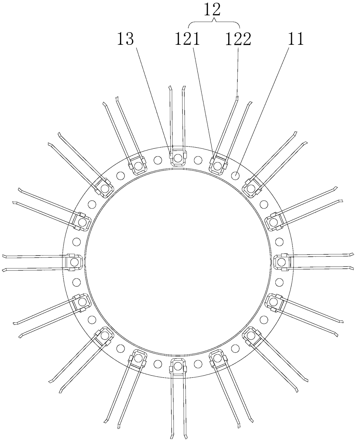
The invention relates to the technical field of zipper head hangers, in particular to a zipper head plating hanger and a manufacturing method thereof. The zipper head electroplating hanger comprises aplurality of hanging loops, a plurality of hanging needles for hanging zipper heads are fixed to the hanging loops, a plurality of connecting rods are further included, the hanging loops are providedwith a plurality of through holes, the connecting rods sequentially pass through the through holes of the multiple hanging loops to be fixedly connected with the hanging loops, and the multiple connecting rods are evenly fixed on the multiple hanging loops arranged at intervals to form a round cage structure. According to the zipper head plating hanger, the hanging loops are provided with the multiple evenly-distributed through holes, the through holes are used for positioning after the hanging loops and the connecting rods are connected, and the positional accuracy of the hanging loops is guaranteed; and the hanging needles are pressed and fixed by pressing pieces, the pressing pieces are also positioned through the through holes, and the positional accuracy of the hanging needles is guaranteed. According to the zipper head plating hanger and the manufacturing method, a stamping forming method is used for manufacturing the hanging loops, and the manufacturing precision of the hangingloops is improved.

Description

technical field [0001] The invention relates to the technical field of zipper puller hangers, in particular to a zipper puller electroplating hanger and a manufacturing method thereof. Background technique [0002] After the semi-finished zipper puller is manufactured, it is usually necessary to hang multiple zipper pullers on a hook or a hook for electroplating to obtain a finished zipper, in order to improve the corrosion resistance of the zipper and prolong the service life of the zipper. Electroplating treatment processes, such as surface cleaning, painting, and electroplating coloring, to obtain clean, beautiful, firm, and rust-proof zipper pulls. In these processing procedures, it is necessary to hang a plurality of zipper pullers on a plurality of hooks or hanging pins and perform synchronously for batch processing. [0003] For example, the patent application number CN201320564859.6 discloses a hanger for zipper slider electroplating, including a hook, a skeleton an...

Claims


Application Information

Patent Timeline
IPC IPC(8): C25D17/08C25D7/02
CPCC25D7/02C25D17/08
Inventor 张天从
Owner 石狮市八九机械设备有限公司
Learn More