
Punching cutting tool

A tool and punching technology, which is applied in the field of punching tools, can solve the problems of broken tool life, waste stuck on the inner hole of the tool, and safety, and achieve high machining accuracy, reduced deformation, and long service life. Effect

Inactive Publication Date: 2018-12-18
TAICANG RONGZHONG ELECTRIC CO LTD
View PDF0 Cites 0 Cited by
  • Summary
  • Abstract
  • Description
  • Claims
  • Application Information

AI Technical Summary

Problems solved by technology

[0002] When punching rubber products or metal sheets, the scraps at the punching part of the workpiece often get stuck on the inner hole of the tool and need to be cleaned manually, otherwise the quality of punching will be affected again. Manual cleaning is not only time-consuming and laborious, but also has potential safety hazards. , the traditional punching tool cannot reach a certain hardness when it is used for punching special materials in the selection of materials, and the problems of knife breakage and short service life of the tool often occur

Method used


Image

  • Punching cutting tool

Examples


Embodiment Construction

[0012] Below, the present invention will be further described in conjunction with the accompanying drawings and specific embodiments.

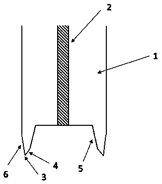
[0013] Such as figure 1 As shown, a punching tool includes a tool matrix 1, a knife tip 3, an outer edge surface 6, a knife edge surface 4 and a knife body surface 5, wherein the tool matrix 1 is a cylindrical Cr12, and there is a vent hole 2 in the middle of the tool matrix 1. The first acute angle formed by the blade surface 4 and the outer edge surface 6 is the tip 3, and the second acute angle formed by the blade surface 5 and the outer edge surface 6 of the tool is smaller than the first acute angle formed by the blade surface 4 and the outer edge surface 6. Acute angle.

[0014] Further, the acute angle formed by the blade edge surface 4 and the outer edge surface 6 is between 15-25 degrees.

[0015] Further, the acute angle formed by the blade surface 5 and the outer edge surface 6 is between 5-10 degrees.

[0016] Further, the cutti...


PUM

PropertyMeasurementUnit
angleaaaaaaaaaa
angleaaaaaaaaaa

Abstract

The invention discloses a punching cutting tool. A cutting tool parent body is a cylindrical Cr12. A ventilation hole is formed in the middle of the cutting tool parent. A first sharp angle formed bya cutting tool point surface and an outer edge surface is arranged to be a cutting tool nose. The angle of a second sharp angle formed by a cutting tool body surface and the outer edge surface of thecutting tool is less than the angle of the first sharp angle formed by the cutting tool point surface and the outer edge surface. The sharp angle formed by the cutting tool point surface and the outeredge surface is between 15 and 25 degrees. The sharp angle formed by the cutting tool body surface and the outer edge surface is between 5 and 10 degrees. The cutting tool parent body needs to be subjected to heat processing after machining. The punching cutting tool is simple in structure. Through arrangement of the ventilation hole in the cutting tool parent body, waste material stuck on a cutting tool head can be automatically ejected out by connecting air pressure, and application is convenient. After the Cr12 is subjected to heat processing, achieved hardness is capable of dealing with different punching metal materials. The service life is long, and machining accuracy is high.

Description

technical field [0001] The invention relates to a mechanical cutter, in particular to a punching cutter. Background technique [0002] When punching rubber products or metal sheets, the scraps at the punching part of the workpiece often get stuck on the inner hole of the tool and need to be cleaned manually, otherwise the quality of punching will be affected again. Manual cleaning is not only time-consuming and laborious, but also has potential safety hazards. , The traditional punching tool cannot reach a certain hardness when it is used to punch special materials in the selection of materials, and problems such as broken tools and short service life of the tool often occur. Contents of the invention [0003] The technical problem solved by the present invention is to provide a punching tool to solve the problems raised in the background technology above. [0004] The object of the present invention adopts following technical scheme to realize: [0005] A punching tool,...

Claims


Application Information

Patent Timeline
Patent Type & Authority Applications(China)
IPC IPC(8): B26F1/16B26D7/08B21D28/34B08B5/02
CPCB26F1/16B08B5/02B21D28/34B26D7/088
Inventor 符建豪
Owner TAICANG RONGZHONG ELECTRIC CO LTD
Learn More