Parallel multi-channel numerical control machine tool

A CNC machine tool, multi-channel technology, applied in metal processing machinery parts, metal processing equipment, feeding devices, etc., can solve the problems of position shielding, untidy beam grooves, unfavorable design layout and assembly maintenance, etc. less, improve processing efficiency, and is conducive to the effect of design layout and assembly maintenance

Active Publication Date: 2018-12-18
江西衡源智能装备股份有限公司
View PDF8 Cites 2 Cited by
  • Summary
  • Abstract
  • Description
  • Claims
  • Application Information

AI Technical Summary

Problems solved by technology

[0007] In addition, the servo motor and its sensor cables, as well as the ball screw and the lubrication pipe of the linear guide slider interfere with each other, making the beam groove very untidy, which is not conducive to design layout and assembly maintenance
[0008] Furthermore, for multi-head or multi-channel machine tools, it is necessary to consider how to set up more processing heads and processing channels in a limited size space, because the number of processing heads determines the number of processing channels, and the number of processing channels determines the processing efficiency , and the number of processing heads is determined by the center-to-center distance between the processing heads. Therefore, a reasonable design is required to reduce the center-to-center distance of the processing heads, but a smaller center-to-center distance of the processing heads will make the space between the X slides more compact, thus produce more severe positional occlusion

Method used


Image

  • Parallel multi-channel numerical control machine tool
  • Parallel multi-channel numerical control machine tool
  • Parallel multi-channel numerical control machine tool

Examples


no. 1 approach

[0051] Combine below Figure 1 to Figure 3 The structure of the machine tool according to the first embodiment of the present invention will be described.

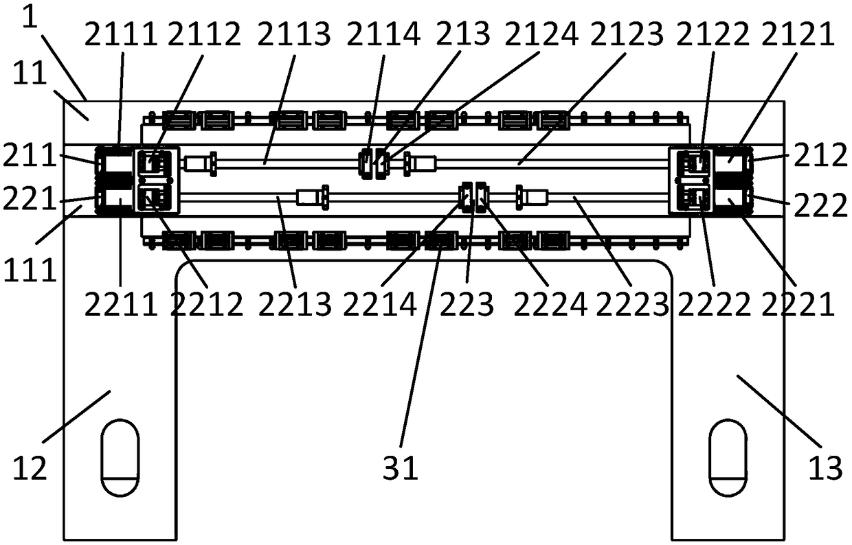
[0052] figure 1 A beam structure diagram of the machine tool according to the first embodiment of the present invention is shown.

[0053] Beam 1

[0054] Such as figure 1 As shown, the beam 1 includes a top beam 11 , a left support column 12 and a right support column 13 , and the left support column 12 and the right support column 13 are fixedly arranged at both ends of the top beam 11 . The beam 1 is in the shape of a door as a whole.

[0055] A beam groove 111 is opened on the front surface of the top beam 11 , and a ball screw transmission mechanism 2 is arranged in the beam groove 111 .

[0056] Ball screw drive mechanism 2

[0057] Such as Figure 1 to Figure 3 As shown, in this embodiment, the ball screw transmission mechanism 2 includes a first pair of ball screw transmission mechanisms 21 and a second pair...

no. 2 approach

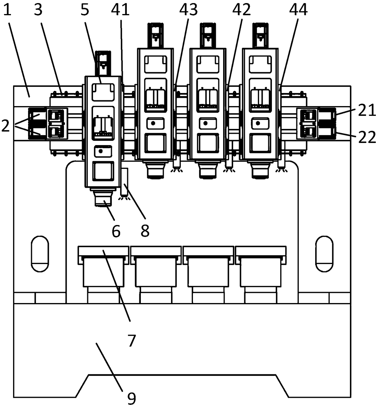
[0096] Figure 4 A beam structure diagram of a machine tool according to a second embodiment of the present invention is shown.

[0097] The beam 1, linear guide rail 3, horizontal slide 4, vertical slide 5, processing head 6, longitudinal table 7, online measuring device 8 and bed 9 in the second embodiment are the same as the beam 1 in the first embodiment. , linear guide rail 3, horizontal slide plate 4, vertical slide plate 5, processing head 6, longitudinal workbench 7, on-line measuring device 8, and bed 9 are roughly the same in structure, and the following mainly introduces the differences between this embodiment and the first embodiment place.

[0098] The difference between this embodiment and the first embodiment mainly lies in the structure of the motor driving mechanism in the ball screw transmission mechanism 2 , which will be described in detail below.

[0099] As mentioned in the first embodiment, if the first left lateral slide plate 41 is arranged on the le...

no. 3 approach

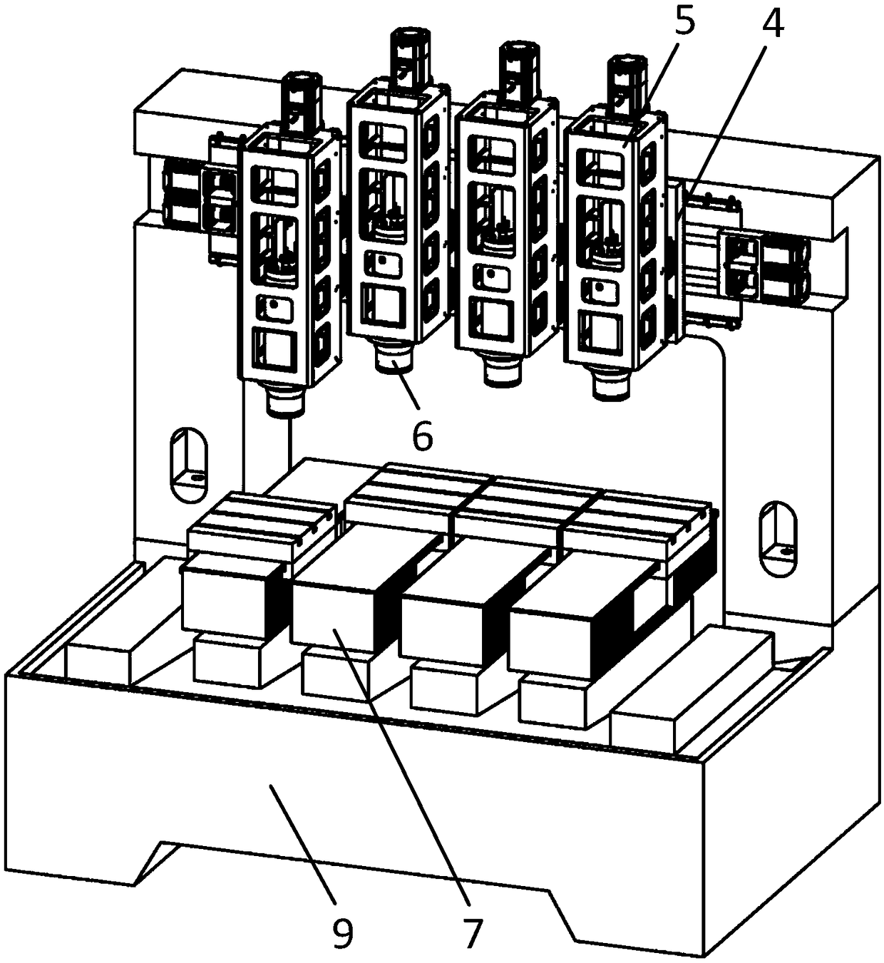
[0104] Figure 5 A beam structure diagram of a machine tool according to a third embodiment of the present invention is shown.

[0105] The beam 1, linear guide rail 3, horizontal slide 4, vertical slide 5, processing head 6, longitudinal table 7, online measuring device 8 and bed 9 in the third embodiment are the same as the beam 1 in the first embodiment. , linear guide rail 3, horizontal slide plate 4, vertical slide plate 5, processing head 6, longitudinal workbench 7, on-line measuring device 8 and bed 9 are basically the same in structure respectively, and the following mainly introduces the differences between this embodiment and the first embodiment the difference.

[0106] The difference between this embodiment and the first embodiment mainly lies in the structure of the ball screw transmission mechanism 2, which will be described in detail below.

[0107] In this embodiment, by increasing the vertical width dimension of the beam groove 111 , a third pair of ball sc...


PUM


Abstract

The invention relates to a parallel multi-channel numerical control machine. The numerical control machine tool comprises a cross beam, at least two ball screw transmission mechanisms which are arranged in parallel up and down are arranged on the front side of the cross beam, each ball screw transmission mechanism comprises a left ball screw transmission mechanism body and a right ball screw transmission mechanism body, each left ball screw transmission mechanism body comprises a left ball screw and a left motor drive mechanism arranged at the left end of the cross beam, the right end of eachleft motor drive mechanism is connected with the left end of the corresponding left ball screw, each right ball screw transmission mechanism body comprises a right ball screw and a right motor drive mechanism at the right end of the cross beam, the left end of each right motor drive mechanism is connected with the right end of the corresponding right ball screw, the right end of each left ball screw is opposite to the left end of the corresponding right ball screw at a reserved position, and the reserved positions in the at least two ball screw transmission mechanisms are staggered in the transverse direction. The numerical control machine tool can arrange more transverse sliding plates in the limited size space as many as possible

Description

technical field [0001] The invention relates to the field of numerical control machine tools, in particular to a parallel multi-channel numerical control machine tool. Background technique [0002] In the existing technology, the processing of 3C product parts represented by smart phones has a large batch size, a small processing allowance, and a short update cycle. At present, traditional drilling centers and vertical machining centers are generally used for processing, and the processing efficiency is low. , The machine tool occupies a large area, and one machine tool requires one operator. [0003] Patent document CN202640067U (announcement date is January 2, 2013) discloses a multi-axis CNC machine tool. Multiple Z-axes and processing head spindles are arranged on the same X slide plate to form multiple processing stations to achieve high Efficiency processing. However, each machining spindle cannot independently adjust its position, and cannot realize the tool compens...

Claims


Application Information

Patent Timeline
Patent Type & Authority Applications(China)
IPC IPC(8): B23Q5/40
Inventor 吴勇勇王焱陆平刘首男袁海忠
Owner 江西衡源智能装备股份有限公司
Why Eureka
Try Eureka