
A Large Vibration Horn for Ultrasonic High-speed Vibration Assisted Machining

A technology of auxiliary processing and horn, which is applied in the direction of vibrating fluid, metal processing equipment, manufacturing tools, etc., which can solve the problems of affecting broaching efficiency, shortening the service life of tools, and being unable to guarantee a non-interference state, so as to achieve high vibration The effect of speed, prolonging service life and reducing damage

Active Publication Date: 2020-04-07
CENT SOUTH UNIV
View PDF7 Cites 0 Cited by
  • Summary
  • Abstract
  • Description
  • Claims
  • Application Information

AI Technical Summary

Problems solved by technology

It is impossible to guarantee a non-interference state within one vibration frequency cycle - that is, the cutter teeth are completely separated from the workpiece, which affects broaching efficiency and shortens the service life of the tool

Method used


Image

  • A Large Vibration Horn for Ultrasonic High-speed Vibration Assisted Machining
  • A Large Vibration Horn for Ultrasonic High-speed Vibration Assisted Machining
  • A Large Vibration Horn for Ultrasonic High-speed Vibration Assisted Machining

Examples


Embodiment Construction

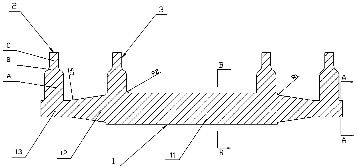
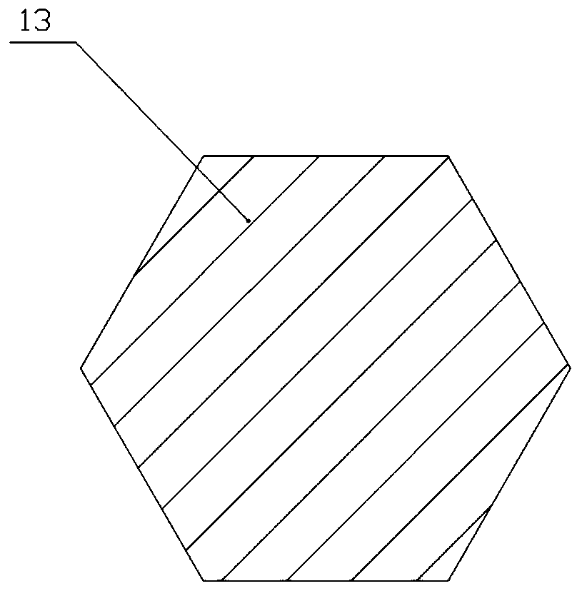
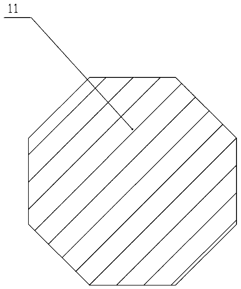
[0028] When the inventor was designing, it was considered that in processing the tenon groove of the turbine disk, since a profile of the tenon groove is a curve (in the X-Y plane), the chip formed during the cutting process is a curved surface. In ultrasonic vibration assisted machining, the tool When vibrating relative to the workpiece along the x and y axes, interference will occur. There is no guarantee that the cutter teeth will be out of contact with the workpiece within one vibration frequency cycle.

[0029] In order to solve the above interference problems, the inventor hopes to control the vibration transmission system in the X, Y, and Z directions in the cutting vibration transmission system to achieve no motion interference, that is, to realize the cutting tool and the workpiece within a part of the cycle. Completely out of contact in x, y, z directions. Therefore, according to the vibration characteristics, the inventor designed this device, which can controllabl...


PUM


Abstract

The invention discloses a high-amplitude vibration amplitude variable rod for ultrasonic high-speed vibration auxiliary processing. The high-amplitude vibration amplitude variable rod is a whole pieceand includes a main body rod and a plurality of amplitude variable rod bodies, the main body rod is a diameter variable rod arranged in the length direction of a tool workbench, the amplitude variable rod bodies are the amplitude variable rod bodies with the rod diameter reducing from the tool workbench to a cutter pulling cutter box, and the bottom end of each amplitude variable rod body is connected to the variable diameter position of the main body rod. When used, the energy can be concentrated on a smaller area because the rod diameter of each amplitude variable rod body reduces from thevibration penetrating-in end to the transferring-out end, the vibration is amplified and transmitted to the cutter pulling cutter box and a pulling cutter, the high vibration speed is achieved, high vibration speed requirements when a turbine disk tenon groove is processed are met, and the surface quality is improved; and the amplitude is enlarged, the fact that cutter teeth are completely separated from a workpiece within a vibration frequency cycle, the possibility of a tool hitting the workpiece when the tool is returned from a non-cut-off material is avoided, the machining efficiency can be improved, the damage caused by the interference to the tool can be reduced, and the service life of the tool is prolonged.

Description

technical field [0001] The invention belongs to the field of broaching processing equipment, in particular to a large-value vibration horn used for ultrasonic high-speed vibration auxiliary processing. Background technique [0002] In the tenon and groove machining of turbine discs, due to the complex surface of the tenon and groove and high precision requirements, in order to meet the requirements, broaches with different tooth shapes and geometric profiles need to be used during the machining process, and the vibration of the system during the machining process, the wear of the tool There are more stringent requirements, and factors such as the difficult-to-machine characteristics of nickel-based alloys as the material of the additional turbine disk will have an impact on the high-efficiency broaching of the turbine disk tenon and groove. However, the cutting force in broaching is much larger than that of ordinary turning and milling, which puts forward higher requirements...

Claims


Application Information

Patent Timeline
Patent Type & Authority Patents(China)
IPC IPC(8): B06B3/02B23D39/00
CPCB06B3/02B23D39/00
Inventor 唐进元陈雪林丁撼
Owner CENT SOUTH UNIV
Learn More